Nubira-Lacetti |
||||||||
|
||||||||
| Step | Action | Value(s) | Yes | No |
| 1 |
Perform an On-Board Diagnostic (EOBD) System Check.
Was the check performed?
|
-
|
Go to Step 2
|
|
| 2 |
Are any component Diagnostic Trouble Codes (DTCs) set?
|
-
|
Go to
applicable DTC tables
|
Go to Step 3
|
| 3 |
Visually/physically check the following:
Is a problem found?
|
-
|
Go to Step 4
|
Go to Step 5
|
| 4 |
Repair the exhaust system as needed.
Is the repair complete?
|
-
|
Go to Step 6
|
-
|
| 5 |
Replace the Three Way Catalytic Converter (TWC).
Is the repair complete?
|
-
|
Go to Step 6
|
-
|
| 6 |
Does the scan tool indicate that this diagnostic has run and passed?
|
-
|
Go to Step 7
|
Go to Step 2
|
| 7 |
Check if any additional DTCs are set.
Are any DTCs displayed that have not been diagnosed?
|
-
|
Go to Applicable DTC table
|
System OK
|

| Step | Action | Value(s) | Yes | No |
| 1 |
Perform an On-Board Diagnostic (EOBD) System Check.
Was tht check Performed?
|
-
|
Go to Step 2
|
|
| 2 |
Does the Actual EGR Position follow the Desired
EGR Position?
|
25%, 50%, 75%, 100%
|
Go to Step 13
|
Go to Step 3
|
| 3 |
Is the Actual EGR Position near the specified value?
|
100%
|
Go to Step 4
|
Go to Step 5
|
| 4 |
Check the signal circuit terminal 3 at the EGR wiring harness connector for a short to voltage and repair as needed.
Is a repair complete?
|
-
|
Go to Step 13
|
Go to Step 6
|
| 5 |
With a voltmeter connected to the ground, probe the 5 volt reference circuit at terminal 4 of the EGR valve wiring harness connector.
Is the voltage near the specified value?
|
5 v
|
Go to Step 7
|
Go to Step 8
|
| 6 |
Is the repair complete?
|
-
|
Go to Step 13
|
-
|
| 7 |
With a teat light connected to ground, probe the EGR valve wiring harness connector terminal 1.
Does the test light illuminate?
|
-
|
Go to Step 9
|
Go to Step 10
|
| 8 |
Check the 5 volt reference circuit for a short to voltage and repair as needed.
Is a repair complete?
|
-
|
Go to Step 13
|
Go to Step 6
|
| 9 |
Check the control circuit for a short to voltage and repair as needed.
Is the repair complete?
|
-
|
Go to Step 13
|
Go to Step 6
|
| 10 |
Check the EGR ground circuit for an open or poor connection at the EGR valve harness connector and repair as needed.
Is a repair necessary.
|
-
|
Go to Step 13
|
Go to Step 12
|
| 11 |
Is the repair complete?
|
-
|
Go to Step 13
|
-
|
| 12 |
Check the ECM connector for a poor connection and
repair as needed.
Is the repair complete?
|
-
|
Go to Step 13
|
-
|
| 13 |
Does the scan tool indicate that this diagnostic ran and passed?
|
-
|
Go to Step 14
|
Go to Step 2
|
| 14 |
Check if any additional DTCs are set.
Are any DTCs displayed that have not been diagnosed?
|
-
|
Go to Applicable DTC table
|
System OK
|

| Step | Action | Value(s) | Yes | No |
| 1 |
Perform an On-Board Diagnostic (EOBD) System Check.
Was the check performed?
|
-
|
Go to Step 2
|
|
| 2 |
Does the solenoid turn ON and OFF with each command.
|
ON-99% OFF-0%
|
Go to Step 3
|
Go to Step 5
|
| 3 |
Does the current draw measure less than the specified value?
|
0.75 A
|
Go to "Diagnostic Aids"
|
Go to Step 4
|
| 4 |
Does the ohmmeter display infinite resistance?
|
-
|
Go to Step 12
|
Go to Step 10
|
| 5 |
Does the test light turn ON and OFF with each command?
|
-
|
Go to Step 8
|
Go to Step 6
|
| 6 |
With a test light connected to ground, probe the ignition feed circuit, terminal 1 in the solenoid harness connector.
|
-
|
Go to Step 7
|
Go to Step 11
|
| 7 |
Does the solenoid operate?
|
-
|
Go to Step 9
|
Go to Step 10
|
| 8 |
Check the connections at the solenoid.
Is a problem found and corrected?
|
-
|
Go to Step 14
|
Go to Step 12
|
| 9 |
Check the connections at the ECM.
Is a problem found and corrected?
|
-
|
Go to Step 14
|
Go to Step 13
|
| 10 |
Repair the faulty solenoid control circuit.
Is the repair complete?
|
-
|
Go to Step 14
|
-
|
| 11 |
Repair the faulty solenoid ignition feed circuit.
Is the repair complete?
|
-
|
Go to Step 14
|
- |
| 12 |
Is the repair complete?
|
-
|
Go to Step 14
|
-
|
| 13 |
Is the repair complete?
|
-
|
Go to Step 14
|
-
|
| 14 |
Does the scan tool indicate that this diagnostic has run and passed?
|
-
|
Go to Step 15
|
Go to Step 2
|
| 15 |
Check if any additional DTCs are set.
Are any DTCs displayed that have not been diagnosed?
|
-
|
Go to Applicable DTC table
|
System OK
|

| Step | Action | Value(s) | Yes | No |
| 1 |
Perform an On-Board Diagnostic (EOBD) System Check.
Is the system check complete?
|
-
|
Go to Step 2
|
|
| 2 |
Is any of the Diagnostic trouble Codes (DTCs) P0462, P0463 or P0502 set?
|
250 km (155 mile)
|
Go to Applicable DTC table
|
Go to Step 3
|
| 3 |
Is the voltage within the specified value?
|
4-5 volts
|
Go to Step 4
|
Go to Step 5
|
| 4 |
Is the repair complete?
|
-
|
Go to Step 10
|
Go to Step 6
|
| 5 |
Using a voltmeter, measure the voltage at the ECM connector terminal K34 by back-probing the ECM connector.
Is the voltage within the specified value?
|
4-5 V
|
Go to Step 8
|
Go to Step 9
|
| 6 |
Does the fuel level sensor vale on the scan tool increase and then decrease steadily when the float is moved?
|
-
|
Go to "Diagnostic Aids"
|
Go to Step 7
|
| 7 |
|
-
|
Go to Step 10
|
-
|
| 8 |
Is the repair complete?
|
-
|
Go to Step 10
|
-
|
| 9 |
Is the repair complete?
|
-
|
Go to Step 10
|
-
|
| 11 |
Does the scan tool indicate that this diagnostic ran and passed?
|
-
|
Go to Step 11
|
Go to Step 2
|
| 12 |
Check if any additional DTCs are set.
Are any DTCs displayed that have not been diagnosed?
|
-
|
Go to Applicable DTC table
|
System OK
|
| Step | Action | Value(s) | Yes | No |
| 1 |
Perform an On-Board Diagnostic (EOBD) System Check.
Was the check performed?
|
-
|
Go to Step 2
|
|
| 2 |
Is Diagnostic trouble Codes (DTCs) P0462 set?
|
-
|
Go to Step 3
|
Go to "Diagnostic Aids"
|
| 3 |
Is the voltage within the specified value?
|
0.4 - 4.5 V
|
Go to Step 4
|
Go to Step 6
|
| 4 |
Check for a proper ground connection at the fuel tank and repair as needed.
Is the repair complete?
|
-
|
Go to Step 11
|
Go to Step 5
|
| 5 |
Does the fuel level sensor vale on the scan tool increase and then decrease steadily when the float is moved?
|
-
|
Go to "Diagnostic Aids"
|
Go to Step 8
|
| 6 |
Check for an open or short to ground in the fuel level sensor circuit and repair as needed.
Is the repair necessary?
|
-
|
Go to Step 11
|
Go to Step 9
|
| 7 |
Repair the open or short to ground in the fuel level sensor circuit between the fuel level sensor harness connector and fuel level sensor.
Is the repair complete?
|
-
|
Go to Step 11
|
-
|
| 8 |
Is the repair complete?
|
-
|
Go to Step 11
|
-
|
| 9 |
Is the voltage within the specified value?
|
4-5 V
|
Go to Step 10
|
|
| 10 |
Is the repair complete?
|
-
|
Go to Step 11
|
-
|
| 11 |
Does the scan tool indicate that this diagnostic has run and passed?
|
-
|
Go to Step 12
|
Go to Step 2
|
| 12 |
Check if any additional DTCs are set.
Are any DTCs displayed that have not been diagnosed?
|
-
|
Go to Applicable DTC table
|
System OK
|
| Step | Action | Value(s) | Yes | No |
| 1 |
Perform an On-Board Diagnostic (EOBD) System Check.
Was the check performed?
|
-
|
Go to Step 2
|
|
| 2 |
Is Diagnostic trouble Codes (DTCs) P0463 set?
|
-
|
Go to Step 3
|
Go to "Diagnostic Aids"
|
| 3 |
Is the voltage within the specified value?
|
0.4 - 4.5 V
|
Go to Step 4
|
Go to Step 6
|
| 4 |
Check for a proper ground connection at the fuel tank and repair as needed.
Is the repair necessary?
|
-
|
Go to Step 11
|
Go to Step 5
|
| 5 |
Does the fuel level sensor vale on the scan tool increase and then decrease steadily when the float is moved?
|
-
|
Go to "Diagnostic Aids"
|
Go to Step 8
|
| 6 |
Check for short to voltage in the fuel level sensor circuit and repair as needed.
Is the repair necessary?
|
-
|
Go to Step 7
|
Go to Step 9
|
| 7 |
Repair the short to voltage in the fuel level sensor circuit between the fuel level sensor harness connector and fuel level sensor.
Is the repair necessary?
|
-
|
Go to Step 11
|
-
|
| 8 |
Is the repair complete?
|
-
|
Go to Step 11
|
-
|
| 9 |
Is the voltage within the specified value?
|
0.4 - 4.5 V
|
Go to Step 10
|
|
| 10 |
Is the repair complete?
|
-
|
Go to Step 11
|
-
|
| 11 |
Does the scan tool indicate that this diagnostic has run and passed?
|
-
|
Go to Step 12
|
Go to Step 2
|
| 12 |
Check if any additional DTCs are set.
Are any DTCs displayed that have not been diagnosed?
|
-
|
Go to Applicable DTC table
|
System OK
|
| Step | Action | Value(s) | Yes | No |
| 1 |
Perform an On-Board Diagnostic (EOBD) System Check.
Was the check performed?
|
-
|
Go to Step 2
|
|
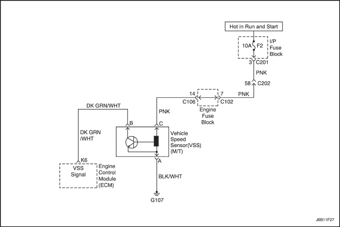
| 2 |
Notice : Running the vehicle in gear with the wheels hanging down at full travel will damage the drive axles.
Does the scan tool display vehicle speed above the specific value?
|
0 mph
|
Go to Step 3
|
Go to Step 4
|
| 3 |
Does the scan tool display vehicle speed above the specific value?
|
0 mph
|
Go to Step 12
|
Go to Step 4
|
| 4 |
Is the voltage near the specified value?
|
10.1 v
|
Go to Step 5
|
Go to Step 7
|
| 5 |
Using a voltmeter connected to ground, measure the voltage at terminal C of the VSS connector.
Is the voltage near the specified value?
|
11-14 V
|
Go to Step 6
|
Go to Step 8
|
| 6 |
Using a ohmmeter connected to ground, measure the voltage at terminal A of the VSS connector.
Is the voltage near the specified value?
|
400 Ω
|
Go to Step 10
|
Go to Step 9
|
| 7 |
Check the VSS signal circuit for an open or short to ground and repair as needed.
Is the repair complete?
|
-
|
Go to Step 12
|
Go to Step 11
|
| 8 |
Check the ignition circuit for an open and repair as needed.
Is the repair complete?
|
-
|
Go to Step 12
|
-
|
| 9 |
Check the VSS ground circuit for an open and repair as needed.
Is the repair complete?
|
-
|
Go to Step 12
|
-
|
| 10 |
Is the repair complete?
|
-
|
Go to Step 12
|
-
|
| 11 |
Is the repair complete?
|
-
|
Go to Step 12
|
-
|
| 12 |
Does the scan tool indicate that this diagnostic has run and passed?
|
-
|
Go to Step 13
|
Go to Step 2
|
| 13 |
Check if any additional DTCs are set.
Are any DTCs displayed that have not been diagnosed?
|
-
|
Go to Applicable DTC table
|
System OK
|
| © Copyright General Motors Chevrolet Europe. All rights reserved |


