MAINTENANCE AND REPAIR
ON-VEHICLE SERVICE


Center Molding (Notchback)
Removal Procedure
- Disconnect the mode control cable from the mode door.
- Remove the center molding.
- Disconnect the electrical connector.
Installation Procedure
- Connect the mode control cable from the mode door.
- Connect the electrical connector.
- Install the center molding.

Center Molding (Hatchback, S/Wagon)
Removal Procedure
- Disconnect the negative battery cable.
- Pry off the center molding.
- Disconnect the mode control cable from the mode door.
- Disconnect the electrical connector.
- Remove the center molding.
Installation Procedure
- Connect the mode control cable from the mode door.
- Connect the electrical connector.
- Install the center molding.
- Connect the negative battery cable.

Instrument Cluster Trim Panel (Notchback)
Removal Procedure
- Remove the screws and the instrument cluster trim panel.
- Disconnect the electrical connectors.
Installation Procedure
- Connect the electrical connectors.
- Install the instrument cluster trim panel with the screws.

Instrument Cluster Trim Panel (Hatchback, S/Wagon)
Removal Procedure
- Remove the screws and the instrument cluster trim panel.
Installation Procedure
- Install the screws and the instrument cluster trim panel.

Garnish Molding
Removal Procedure
- Remove the glove box.
- Remove the screws and the garnish molding.
Installation Procedure
- Install the garnish molding with the screws.
Tighten
Tighten the garnish molding screw to 2 N•m (18 lb-in).
- Install the glove box.

Ashtray
Removal Procedure
- Remove the instrument panel center molding.
- Remove the screws and the ashtray housing.
Installation Procedure
- Install the ashtray housing with screws.
- Install the instrument panel center molding.

Cigar Lighter
Removal Procedure
- Remove the instrument panel center molding.
- Disconnect the cigar lighter and ashtray lamp electrical connector.
- Remove the cigar lighter housing from the instrument panel.
Installation Procedure
- Install the cigar lighter housing to the instrument panel.
- Install the cigar lighter in the cigar lighter housing.
- Connect the cigar lighter and ashtray lamp electrical connector.
- Install the instrument panel center molding.

Glove Box
Removal Procedure
- Remove the screws and the glove box.
Installation Procedure
- Install the glove box with the screws.

Deposit Box (Notchback)
Removal Procedure
- Remove the glove box.
- Remove the screws and deposit box.
Installation Procedure
- Install the deposit box with the screws.
- Install the glove box.

Digital Clock (Notchback)
Removal Procedure
- Disconnect the negative battery cable.
- Remove the center molding.
- Disconnect the electrical connector.
- Remove the screws and digital clock.
Installation Procedure
- Install the digital clock with the screws.
- Connect the electrical connector.
- Install the center molding.
- Connect the negative battery cable.

Digital Clock (Hatchback, S/Wagon)
Removal Procedure
- Disconnect the negative battery cable.
- Remove the instrument panel center upper cover.
- Remove the screws and the clock.

Installation Procedure
- Install the clock with the screws.
Tighten
Tighten the clock screws to 3 N•m (27 lb-in).
- Install the instrument panel center upper cover.
- Connect the negative battery cable.
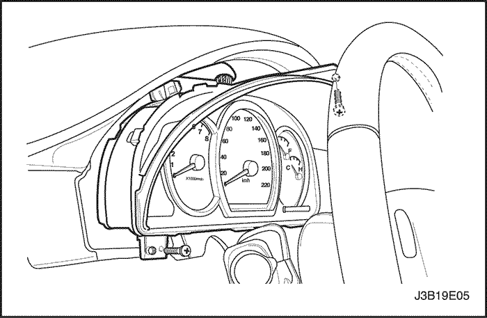
Instrument Cluster
Removal Procedure
- Disconnect the negative battery cable.
- Remove the instrument cluster trim panel.
- Remove the screws and the instrument cluster.
- Disconnect the electrical connectors.
Installation Procedure
- Connect the electrical connectors.
- Install the instrument cluster with the screws.
Tighten
Tighten the instrument cluster screw to 4 N•m (35 lb-in).
- Install the instrument cluster trim panel.
- Connect the negative battery cable.

Instrument Cluster Dimmer Switch
Removal Procedure
- Remove the instrument cluster dimmer switch assembly.
- Disconnect the electrical connectors.
Installation Procedure
- Connect the electrical connectors.
- Install the instrument cluster dimmer switch assembly.

Instrument Cluster Indicator Lamps
Removal Procedure
- Disconnect the negative battery cable.
- Remove the instrument cluster. Refer to "Instrument Cluster"
in this section.
- Remove the defective bulb from the rear of the cluster.
Installation Procedure
- Install the new bulb.
- Install the instrument cluster. Refer to "Instrument Cluster"
in this section.
- Connect the negative battery cable.
Instrument Panel
Removal Procedure
- Disconnect the negative battery cable.
- Remove the floor console. Refer to Section 9G, Interior Trim.
- Remove the sun sensor. Refer to Section 7D, Automatic Temperature Control Heating, Ventilation, and Air Condition System.
- Remove the stereo cassette AM/FM radio. Refer to Section 9F, Audio Systems.
- Remove the center molding.
- Remove the instrument cluster dimmer switch assembly.
- Remove the instrument cluster trim panel. Refer to "Instrument Cluster Trim Panel"
in this section.
- Remove the instrument cluster. Refer to "Instrument Cluster"
in this section.
- Remove the glove box and the glove box housing. Refer to "Glove Box"
in this section.
- Remove the knee bolster. Refer to Section 9G, Interior Trim.

- Remove the screws and the instrument panel side covers.
- Remove the screw and the instrument panel fuse block.

- Remove the nuts and the bolts securing the steering column.
- Disconnect the steering column electrical connector.
- Lower the steering column.

- Remove bolts and screws.
- Remove the connecting pieces.

- Remove the bolt securing the middle of the instrument panel to the body.

- Remove the instrument panel screws behind the glove box brace.

- Remove the bolts securing the sides of the instrument panel to body.
- Disconnect the instrument panel electrical connectors.
- Remove the instrument panel.
Installation Procedure
- Position the instrument panel in the vehicle.
- Connect the instrument panel electrical connectors.
Notice : Dissimilar metals in direct contact with each other may corrode rapidly. Make sure to use the correct fasteners to prevent premature corrosion.
- Install the bolts securing the sides of the instrument panel to the body.
Tighten
Tighten the instrument panel-to-body bolts to 22 N•m (16 lb-ft).
- Install the instrument panel screws behind the glove box brace.
- Install the bolt securing the middle of the instrument panel to the body.
Tighten
Tighten the instrument panel-to-body bolts to 22 N•m (16 lb-ft).
- Install the connecting pieces with bolts and screws.
Tighten
Tighten the connecting pieces bolts to 22 N•m (16 lb-ft).
- Raise the steering column.
- Connect the steering column electrical connector.
- Install the nuts and the bolts securing the steering column.
Tighten
Tighten the steering column nuts to 22 N•m (16 lb-ft).
Tighten the steering column bolts to 22 N•m (16 lb-ft).
- Install the instrument panel fuse block with the screw.
- Install the instrument panel side covers with the screws.

- Install the knee bolster. Refer to Section 9G, Interior Trim.
- Install the glove box and the glove box housing. Refer to "Glove Box"
in this section.
- Install the instrument cluster. Refer to "Instrument Cluster"
in this section.
- Install the instrument cluster trim panel. Refer to "Instrument Cluster Trim Panel"
in this section.
- Install the instrument cluster dimmer switch assembly.
- Install the stereo cassette AM/FM radio. Refer to Section 9F, Audio Systems. Install the center molding.
- Install the sun sensor. Refer to Section 7D, Automatic Temperature Control Heating, Ventilation, and Air Condition System.
- Install the floor console. Refer to Section 9G, Interior Trim.
- Connect the negative battery cable.

Chime Module
(Left-hand Drive Shown, Right-Hand Drive Similar)
Removal Procedure
- Disconnect the negative battery cable.
- Remove the knee bolster trim panel beneath the steering column.
- Disconnect the electrical connector.
- Remove the screws and the chime module.
Installation Procedure
- Install the chime module with the screws.
Tighten
Tighten the chime module screws to 4 N•m (35 lb-in).
- Connect the electrical connector.
- Install the knee bolster trim panel beneath the steering column.
- Connect the negative battery cable.
| © Copyright General Motors Chevrolet Europe. All rights reserved |


