SECTION 9H
SEATS
Caution : Disconnect the negative battery cable before removing or installing any electrical unit or when a tool or equipment could easily come in contact with exposed electrical terminals. Disconnecting this cable will help prevent personal injury and damage to the vehicle. The ignition must also be in LOCK unless otherwise noted.
SPECIFICATIONS
Fastener Tightening Specifications
|
Application
|
N•m
|
Lb-Ft
|
Lb-In
|
|
Armrest Nuts
|
24
|
18
|
-
|
|
Front Seatback Bolts
|
45
|
33
|
-
|
|
Front Seat Cover Screws
|
12
|
-
|
106
|
|
Front Seat Cushion Bolts
|
12
|
-
|
106
|
|
Front Seat Trim Screws
|
12
|
-
|
106
|
|
Front Seat-to-Floor Bolts
|
25
|
18
|
-
|
|
Rear Seatback Bolts
|
25
|
18
|
-
|
|
Rear Seat Hinge Bolts
|
45
|
33
|
-
|
|
Seat Recliner Lever Screw
|
12
|
-
|
106
|
|
Slide Assembly Bolts
|
25
|
18
|
-
|
|
Slide Assembly Screws
|
10
|
-
|
89
|
MAINTENANCE AND REPAIR
ON-VEHICLE SERVICE


Front Bucket Seat
Removal Procedure
- Disconnect the negative battery cable.
- Remove the plastic caps and the bolts securing the rear portion of the front seat to the floor.

- Remove the plastic caps and the bolts securing the front portion of the front seat to the floor.
- Disconnect the electrical connectors.
- Remove the seat.
Installation Procedure
- Install the seat.
- Connect the electrical connectors.
Notice : Dissimilar metals in direct contact with each other may corrode rapidly. Make sure to use the correct fasteners to prevent premature corrosion.
- Install the bolts into the front portion of the front seat.
Tighten
Tighten the front seat-to-floor bolts to 25 N•m (18 lb-ft).
- Install the plastic caps.
-
Install the bolts into the rear portion of the front seat.
Tighten
Tighten the front seat-to-floor bolts to 25 N•m (18 lb-ft).
- Install the plastic caps.
- Connect the negative battery cable.

Front Seatback
Removal Procedure
- Remove the front bucket seat from the vehicle. Refer to "Front Bucket Seats"
in this section.
- Remove the each seat trim.

- Disconnect the electrical connectors.
- Remove the bolts and the seatback.
Installation Procedure
- Install the seatback onto the seat cushion.
Notice : Dissimilar metals in direct contact with each other may corrode rapidly. Make sure to use the correct fasteners to prevent premature corrosion.
- Install the front seatback bolts.
Tighten
Tighten the front seatback bolts to 45 N•m (33 lb-ft).
- Connect the electrical connectors.
- Install the seat trims to its original position.
- Install the front bucket seat in the vehicle. Refer to "Front Bucket Seats"
in this section.

Front Seat Cushion
Removal Procedure
- Remove the front seat from the vehicle. Refer to "Front Bucket Seats"
in this section.
- Remove the seat trims.
- Remove the seat cushion nuts.
- Remove the cushion from the seat track.
Installation Procedure
- Install the cushion onto the seat track.
Notice : Dissimilar metals in direct contact with each other may corrode rapidly. Make sure to use the correct fasteners to prevent premature corrosion.
- Install the seat cushion with the nuts.
Tighten
Tighten the front seat cushion nuts to 12 N•m (106 lb-in).
- Install the seat trims.
- Install the front seat in the vehicle. Refer to "Front Bucket Seats"
in this section.

Lumbar Support Lever
Removal Procedure
- Remove the lumbar support lever.
Installation Procedure
Notice : Dissimilar metals in direct contact with each other may corrode rapidly. Make sure to use the correct fasteners to prevent premature corrosion.
- Install the lumbar support lever.

Height Adjustment Knobs
Removal Procedure
- Remove the height adjustment knob.
Installation Procedure
Notice : Dissimilar metals in direct contact with each other may corrode rapidly. Make sure to use the correct fasteners to prevent premature corrosion.
- Install the height adjustment knob.

Front Seat Trim
Removal Procedure
- Remove the front bucket seat from the vehicle. Refer to "Front Bucket Seats"
in this section.
- Remove the screws and the front seat trim.
Installation Procedure
Notice : Dissimilar metals in direct contact with each other may corrode rapidly. Make sure to use the correct fasteners to prevent premature corrosion.
- Install the front seat trim with the screws.
Tighten
Tighten the front seat trim screws to 12 N•m (106 lb-in).
- Install the front bucket seat in the vehicle. Refer to "Front Bucket Seats"
in this section.

Head Restraint
Removal Procedure
- Press in the head restraint adjust button and remove the head restraint from the seatback.

- Insert two flat head screwdrivers down the front and back side of the guide sleeves.
- With the screwdrivers, press in the retaining latches and remove the guide sleeves.

Installation Procedure
- Install the guide sleeves into the seatback and press them down to engage the guide sleeve retaining latches.
- Install the head restraint into the guide sleeves.

Rear Seat Cushion
Removal Procedure
- Remove the rear seat cushion from the floor by lifting it off of the retaining brackets and sliding it forward.

Installation Procedure
- Install the rear seat cushion by inserting the metal loops into the rear retaining brackets and pressing the front of the seat cushion down.

Split Rear Seatback
Removal Procedure
- Lower the rear seatbacks.
- Remove the bolts, and the seatback from the hinges.
Installation Procedure
Notice : Dissimilar metals in direct contact with each other may corrode rapidly. Make sure to use the correct fasteners to prevent premature corrosion.
- Install the seatback to the hinges with the bolts.
Tighten
Tighten the rear seatback bolts to 25 N•m (18 lb-ft).
- Raise and secure the rear seatbacks in the upright position.
Split Rear Seatback Hinge
Removal Procedure
- Remove the rear seatback and the rear seat cushion. Refer to "Split Rear Seatback"
and "Rear Seat Cushion"
in this section.
- Remove the bolts and the seatback center hinge.
Installation Procedure
Notice : Dissimilar metals in direct contact with each other may corrode rapidly. Make sure to use the correct fasteners to prevent premature corrosion.
- Install the seatback center hinge with the bolts.
Tighten
Tighten the rear seat hinge bolts to 45 N•m (33 lb-ft).
- Install the rear seatback and the rear seat cushion. Refer to "Split Rear Seatback"
and "Rear Seat Cushion"
in this section.

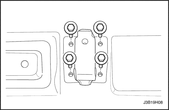
Rear Seat Center Armrest
Removal Procedure
- Lower the rear seatbacks.
- Remove the nuts and the armrest.
Installation Procedure
Notice : Dissimilar metals in direct contact with each other may corrode rapidly. Make sure to use the correct fasteners to prevent premature corrosion.
- Install the armrest with the nuts.
Tighten
Tighten the armrest nuts to 24 N•m (18 lb-ft).
- Raise and secure the rear seatbacks in the upright position.

Seat Covers
Removal Procedure
- Remove the seatback and/or cushion. Refer to "Front Seatback",
"Front Seat Cushion",
"Split Rear Seatback",
and/or "Rear Seat Cushion"
in this section.
- Remove the hog rings from the seatback and/or the cushion.
- Remove the seat cover from the seatback and/or the cushion.
Installation Procedure
- Install the seat cover onto the seatback and/or the cushion with new hog rings.
- Install the seatback and/or the seat cushion. Refer to "Front Seatback",
"Front Seat Cushion",
"Split Rear Seatback",
and/or "Rear Seat Cushion"
in this section.

Notchback Child Seat Anchorage
Removal Procedure
- Remove child seat anchorage cover.
- Remove bolt and the child seat anchorage.
- Remove bolt and the child seat anchorage.
Installation Procedure
- Install the child seat anchorage with the bolt.
Tighten
Tighten the child seat anchorage bolt to 10 N•m (89 lb-in).
- Install the child seat anchorage cover.

Hatchback Child Seat Anchorage
Removal Procedure
- Remove child seat anchorage cover.
- Remove bolt and the child seat anchorage.
- Remove bolt and the child seat anchorage.
Installation Procedure
- Install the child seat anchorage with the bolt.
Tighten
Tighten the child seat anchorage bolt to 10 N•m (89 lb-in).
- Install the child seat anchorage cover.

Station Wagon Child Seat Anchorage
Removal Procedure
- Remove child seat anchorage cover.
- Remove bolt and the child seat anchorage.
- Remove bolt and the child seat anchorage.
Installation Procedure
- Install the child seat anchorage with the bolt.
Tighten
Tighten the child seat anchorage bolt to 10 N•m (89 lb-in).
- Install the child seat anchorage cover.
GENERAL DESCRIPTION
AND SYSTEM OPERATION
Seats
Do not attempt to change the designed seat position by altering the designed seat adjuster-to-floor pan anchor provisions or the seat adjuster-to-seat frame anchor provisions. Changing the seat position could affect the performance of the seat system.
This vehicle is equipped with front bucket seats with separate, adjustable head restraints, and a three-passenger rear bench seat with an optional split folding rear seat. The front bucket seats also have a recline, a height, and a lumbar adjustment. A power driver seat is optional. Seat cushions and seatbacks have formed foam pads, which fit the contours of the full panel seatback frame assembly and the designed contour of the seat cushion frame.


