Nubira-Lacetti |
||||||||
|
||||||||

| Step | Action | Value(s) | Yes | No |
| 1 |
Is the light on at both terminal?
|
-
|
System OK
|
Go to Step 2
|
| 2 |
Is the light on at only one terminal?
|
-
|
Go to Step 3
|
Go to Step 4
|
| 3 |
Repair the open in the wiring between the main relay connector terminal 87 and the fuse Ef11.
Is the repair complete?
|
-
|
System OK
|
-
|
| 4 |
Is the light on at both terminals.
|
-
|
Go to Step 6
|
Go to Step 5
|
| 5 |
Is the resistance within the specified value
|
0 Ω
|
Go to Step 7
|
Go to Step 6
|
| 6 |
Repair open circuit.
Is the repair complete?
|
-
|
System OK
|
-
|
| 7 |
Replace the main relay.
Is the repair complete?
|
-
|
System OK
|
-
|

| Step | Action | Value(s) | Yes | No |
| 1 |
Is the light on at both terminal?
|
-
|
System OK
|
Go to Step 2
|
| 2 |
Is the light on at only one terminal?
|
-
|
Go to Step 3
|
Go to Step 4
|
| 3 |
Repair the open in the wiring between the ignition relay connector terminal 87 and the fuse F2.
Is the repair complete?
|
-
|
System OK
|
-
|
| 4 |
Is the light on at both terminals.
|
-
|
Go to Step 6
|
Go to Step 5
|
| 5 |
Is the resistance within the specified value
|
0 Ω
|
Go to Step 7
|
Go to Step 6
|
| 6 |
Repair open circuit.
Is the repair complete?
|
-
|
System OK
|
-
|
| 7 |
Replace the ignition relay.
Is the repair complete?
|
-
|
System OK
|
-
|

| Step | Action | Value(s) | Yes | No |
| 1 |
Is the difference in the two voltage readings less than the value specified?
|
0.4 v
|
Go to Step 2
|
Go to Step 5
|
| 2 |
Is the difference in voltage readings more than the value specified?
|
1.5 v
|
System OK
|
Go to Step 3
|
| 3 |
Inspect the MAP sensor connector terminals.
Is the problem found?
|
-
|
Go to Step 4
|
Go to Step 5
|
| 4 |
Repair the MAP sensor connector terminals as needed.
Is the repair complete?
|
-
|
System OK
|
-
|
| 5 |
Replace the MAP sensor.
Is the repair complete?
|
-
|
System OK
|
-
|
| Step | Action | Value(s) | Yes | No |
| 1 |
Perform an On-Board Diagnostic (EOBD) System Check.
Is the system check complete?
|
-
|
Go to Step 2
|
|
| 2 |
Turn the ignition switch to ON.
Is the Malfunction Indicator Lamp (MIL) on steady?
|
-
|
Go to Step 4
|
Go to Step 3
|
| 3 |
Turn the ignition switch to LOCK.
Connect the scan tool to the DLC.
Turn the Turn the ignition switch to ON.
Are any diagnostic trouble codes (DTCs) displayed?
|
-
|
Go to Step 4
|
Try with another scan tool
|
| 4 |
Refer to the applicable DTC table.
Is only one DTC identified as valid trouble code P0122?
|
-
|
Go to Step 5
|
Go to applicable DTC table and go to "Multiple DTC"
|
| 5 |
Does the scan tool show the TPS voltage change smoothly within the value specified?
|
0.3V-4.8V
|
Go to "Diagnostic Aids"
|
Go to Step 6
|
| 6 |
Does the voltage measure within the value specified?
|
4.8V-5.0V
|
Go to Step 7
|
Go to Step 8
|
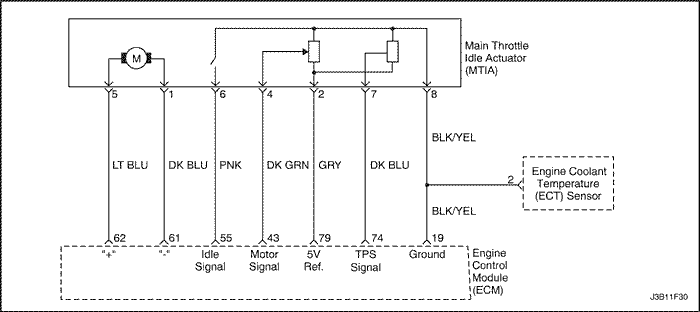
| 7 |
Connect a fused jumper between the MTIA connector terminal 2 and terminal 7.
Does the scan tool show the TPS voltage above value specified?
|
4.8V-5.0V
|
Go to Step 13
|
Go to Step 11
|
| 8 |
Measure the voltage between the MTIA connector 2 and ground.
Does the voltage measure within the value specified?
|
>5.0V
|
Go to Step 9
|
Go to Step 10
|
| 9 |
Is the problem found?
|
-
|
Go to Step 12
|
Go to Step 14
|
| 10 |
Is the problem found?
|
-
|
Go to Step 12
|
Go to Step 14
|
| 11 |
Is the problem found?
|
-
|
Go to Step 12
|
Go to Step 14
|
| 12 |
Is the repair complete?
|
-
|
System OK
|
-
|
| 13 |
Is the repair complete?
|
-
|
System OK
|
-
|
| 14 |
Is the repair complete?
|
-
|
Go to Step 15
|
-
|
| 15 |
Check if any additional DTCs are set.
Are any DTCs displaced that have not been diagnosed?
|
-
|
Go to applicable DTC table
|
System OK
|

| Step | Action | Value(s) | Yes | No |
| 1 |
Perform an On-Board Diagnostic (EOBD) system check.
Was the check performed?
|
-
|
Go to Step 2
|
|
| 2 |
Is the problem found?
|
-
|
Go to Step 3
|
Go to Step 4
|
| 3 |
Clean the IAC passages.
Is the repair complete?
|
-
|
System OK
|
-
|
| 4 |
Measure the resistance between following terminals of IAC valve.
Does the resistance equal to the value specified?
|
40-80
|
Go to Step 6
|
Go to Step 5
|
| 5 |
Replace the IAC valve.
Is the repair complete?
|
-
|
System OK
|
-
|
| 6 |
Is the problem found?
|
-
|
Go to Step 8
|
Go to Step 7
|
| 7 |
Repair an open or short circuit as needed.
Is the repair complete?
|
-
|
System OK
|
-
|
| 8 |
Inspect the IAC connector terminals and the ECM connector terminals.
Is the problem found?
|
-
|
Go to Step 9
|
Go to Step 10
|
| 9 |
Repair or replace the throttle body assembly and/or ECM connector terminals as needed.
Is the repair complete?
|
-
|
System OK
|
-
|
| 10 |
Replace the ECM.
Is the repair complete?
|
-
|
System OK
|
-
|

| Step | Action | Value(s) | Yes | No |
| 1 |
Is the repair complete?
|
-
|
System OK
|
Go to Step 2
|
| 2 |
Check for the presence of spark from all of the ignition wires while cranking the engine.
Is spark present from all of the ignition wires?
|
-
|
System OK
|
Go to Step 3
|
| 3 |
Is spark present from all of the ignition wires?
|
30,000 Ω
|
System OK
|
Go to Step 4
|
| 4 |
Is spark present from at least one of the ignition wires, but not all of the ignition wires?
|
-
|
Go to Step 5
|
Go to Step 12
|
| 5 |
Does the voltage fluctuate within the values specified?
|
0.2-2.0 v
|
Go to Step 6
|
Go to Step 7
|
| 6 |
While cranking the engine, measure the voltage at the EI system ignition coil connector terminal 1.
Does the voltage fluctuate within the values specified?
|
0.2-2.0 v
|
Go to Step 10
|
Go to Step 8
|
| 7 |
Check for an open in the wire from the EI system ignition coil connector terminal 1 to the engine control module (ECM) connector terminal 31.
Is the problem found?
|
-
|
Go to Step 9
|
Go to Step 11
|
| 8 |
Check for an open in the wire from the EI system ignition coil connector terminal 1 to the ECM connector terminal 32.
Is the problem found?
|
-
|
Go to Step 9
|
Go to Step 11
|
| 9 |
Is spark present from all of the ignition wires?
|
-
|
System OK
|
-
|
| 10 |
Is spark present from all of the ignition wires?
|
-
|
System OK
|
-
|
| 11 |
Is spark present from all of the ignition wires?
|
-
|
System OK
|
-
|
| 12 |
Is the resistance within the value specified?
|
400-600 Ω
|
Go to Step 13
|
Go to Step 28
|
| 13 |
Is the repair complete?
|
-
|
Go to Step 14
|
Go to Step 28
|
| 14 |
Is the voltage within the value specified?
|
1.3-1.5 v
(2.4-2.7 v)*
|
Go to Step 20
|
Go to Step 15
|
| 15 |
Measure the voltage between the CKP sensor connector terminal 1 and ground.
Is the voltage within the value specified?
|
1.3-1.5 v
(2.4-2.7 v)*
|
Go to Step 17
|
Go to Step 16
|
| 16 |
Check the wire between the CKP sensor connector terminal 1 and the ECM connector terminal 85 for an open or short.
Is the problem found?
|
- |
Go to Step 18
|
Go to Step 11
|
| 17 |
Check the wire between the CKP sensor connector terminal 3 and ground for an open or short.
Is the problem found?
|
-
|
Go to Step 19
|
Go to Step 11
|
| 18 |
Repair the wire between the CKP sensor connector terminal 1 and the ECM connector terminal 85.
Is the repair complete?
|
-
|
System OK
|
-
|
| 19 |
Repair the wire between the CKP sensor connector terminal 3 and ground.
Is the repair complete?
|
-
|
System OK
|
-
|
| 20 |
Is the voltage within the value specified?
|
1.3-1.5 v
(2.4-2.7 v)*
|
Go to Step 24
|
Go to Step 21
|
| 21 |
Measure the voltage between the CKP sensor connector terminal 2 and ground.
Is the voltage within the value specified?
|
1.3-1.5 v
(2.4-2.7 v)*
|
Go to Step 17
|
Go to Step 22
|
| 22 |
Check the wire between the CKP sensor connector terminal 2 and the ECM connector terminal 54 for an open or short.
Is the problem found?
|
-
|
Go to Step 23
|
Go to Step 11
|
| 23 |
Repair the wire between the CKP sensor connector terminal 2 and the ECM connector terminal 54.
Is the repair complete?
|
-
|
System OK
|
-
|
| 24 |
Is the test light on?
|
-
|
Go to Step 25
|
Go to Step 26
|
| 25 |
Connect a test light between the EI system ignition coil connector terminal 2 and battery positive.
Is the test light on?
|
-
|
Go to Step 5
|
Go to Step 27
|
| 26 |
Check for an open or short to ground in the wiring between the EI system ignition coil connector, terminal 2 and the ignition switch.
Is the problem found?
|
-
|
Go to Step 29
|
-
|
| 27 |
Repair the wire between the EI system ignition coil connector terminal 1 and ground.
Is the repair complete?
|
-
|
System OK
|
-
|
| 28 |
Is the repair complete?
|
-
|
System OK
|
-
|
| 29 |
Replace the fuse F2 or repair the open in the wiring between the EI system ignition coil connector terminal 2 and the ignition switch.
Is the repair complete?
|
-
|
System OK
|
-
|

| Step | Action | Value(s) | Yes | No |
| 1 |
Is the repair complete?
|
-
|
System OK
|
Go to Step 2
|
| 2 |
Check for the presence of spark from all of the ignition wires while cranking the engine.
Is spark present from all of the ignition wires?
|
-
|
System OK
|
Go to Step 3
|
| 3 |
Is spark present from all of the ignition wires?
|
30,000 Ω
|
System OK
|
Go to Step 4
|
| 4 |
Is spark present from at least one of the ignition wires, but not all of the ignition wires?
|
-
|
Go to Step 5
|
Go to Step 12
|
| 5 |
Does the voltage fluctuate within the values specified?
|
0.2-2.0 v
|
Go to Step 6
|
Go to Step 7
|
| 6 |
While cranking the engine, measure the voltage at the EI system ignition coil connector terminal A.
Does the voltage fluctuate within the values specified?
|
0.2-2.0 v
|
Go to Step 10
|
Go to Step 8
|
| 7 |
Check for an open in the wire from the EI system ignition coil connector terminal C to the engine control module (ECM) connector terminal M35 or M51.
Is the problem found?
|
-
|
Go to Step 9
|
Go to Step 11
|
| 8 |
Check for an open in the wire from the EI system ignition coil connector terminal A to the ECM connector terminal M1 or M33.
Is the problem found?
|
-
|
Go to Step 9
|
Go to Step 11
|
| 9 |
Is spark present from all of the ignition wires?
|
-
|
System OK
|
-
|
| 10 |
Is spark present from all of the ignition wires?
|
-
|
System OK
|
-
|
| 11 |
Is spark present from all of the ignition wires?
|
-
|
System OK
|
-
|
| 12 |
Is the resistance within the value specified?
|
400-600 Ω
|
Go to Step 13
|
Go to Step 28
|
| 13 |
Is the repair complete?
|
-
|
Go to Step 14
|
Go to Step 28
|
| 14 |
Is the voltage within the value specified?
|
1.3-1.5 v
(2.4-2.7 v)*
|
Go to Step 20
|
Go to Step 15
|
| 15 |
Measure the voltage between the CKP sensor connector terminal 1 and ground.
Is the voltage within the value specified?
|
1.3-1.5 v
(2.4-2.7 v)*
|
Go to Step 17
|
Go to Step 16
|
| 16 |
Check the wire between the CKP sensor connector terminal 1 and the ECM connector terminal M21 for an open or short.
Is the problem found?
|
- |
Go to Step 18
|
Go to Step 11
|
| 17 |
Check the wire between the CKP sensor connector terminal 3 and ground for an open or short.
Is the problem found?
|
-
|
Go to Step 19
|
Go to Step 11
|
| 18 |
Repair the wire between the CKP sensor connector terminal 1 and the ECM connector terminal M21.
Is the repair complete?
|
-
|
System OK
|
-
|
| 19 |
Repair the wire between the CKP sensor connector terminal 3 and ground.
Is the repair complete?
|
-
|
System OK
|
-
|
| 20 |
Is the voltage within the value specified?
|
1.3-1.5 v
(2.4-2.7 v)*
|
Go to Step 24
|
Go to Step 21
|
| 21 |
Measure the voltage between the CKP sensor connector terminal 2 and ground.
Is the voltage within the value specified?
|
1.3-1.5 v
(2.4-2.7 v)*
|
Go to Step 17
|
Go to Step 22
|
| 22 |
Check the wire between the CKP sensor connector terminal 2 and the ECM connector terminal M5 for an open or short.
Is the problem found?
|
-
|
Go to Step 23
|
Go to Step 11
|
| 23 |
Repair the wire between the CKP sensor connector terminal 2 and the ECM connector terminal M5.
Is the repair complete?
|
-
|
System OK
|
-
|
| 24 |
Is the test light on?
|
-
|
Go to Step 25
|
Go to Step 26
|
| 25 |
Connect a test light between the EI system ignition coil connector terminal B and battery positive.
Is the test light on?
|
-
|
Go to Step 5
|
Go to Step 27
|
| 26 |
Check for an open or short to ground in the wiring between the EI system ignition coil connector, terminal B and the ignition switch.
Is the problem found?
|
-
|
Go to Step 29
|
-
|
| 27 |
Repair the wire between the EI system ignition coil connector terminal C and ground.
Is the repair complete?
|
-
|
System OK
|
-
|
| 28 |
Is the repair complete?
|
-
|
System OK
|
-
|
| 29 |
Replace the fuse Ef10 or repair the open in the wiring between the EI system ignition coil connector terminal B and the ignition switch.
Is the repair complete?
|
-
|
System OK
|
-
|

| Step | Action | Value(s) | Yes | No |
| 1 |
Perform an On-Board Diagnostic (EOBD) system check.
Is the check completed?
|
-
|
Go to Step 2
|
|
| 2 |
Is the fuse OK?
|
-
|
Go to Step 3
|
Go to "Diagnostic Aids"
|
| 3 |
Is the fuse OK?
|
-
|
Go to Step 4
|
Go to "Diagnostic Aids"
|
| 4 |
Do the cooling fans run at low speed?
|
-
|
Go to Step 5
|
Go to Step 10
|
| 5 |
Do the cooling fans run at high speed?
|
-
|
Go to Step 6
|
Go to Step 33
|
| 6 |
Does the A/C compressor clutch engage?
|
-
|
Go to Step 8
|
Go to Step 7
|
| 7 |
Does the A/C compressor clutch engage?
|
-
|
Go to Step 8
|
-
|
| 8 |
Do the cooling fans run at low speed?
|
-
|
Go to Step 9
|
Go to Step 31
|
| 9 |
Do the cooling fans run at high speed?
|
-
|
Go to Step 10
|
-
|
| 10 |
Is the test light on?
|
-
|
Go to Step 11
|
Go to Step 12
|
| 11 |
Is the test light on?
|
-
|
Go to Step 28
|
Go to Step 17
|
| 12 |
Is the test light on?
|
-
|
Go to Step 13
|
Go to Step 24
|
| 13 |
Do the cooling fans run at low speed?
|
-
|
Go to Step 30
|
Go to Step 14
|
| 14 |
Check for an open wire between the low speed cooling fan relay connector terminal 85 and the ECM connector terminal 10.
Is the problem found?
|
-
|
Go to Step 25
|
Go to Step 15
|
| 15 |
Is the test light on?
|
-
|
Go to Step 16
|
Go to Step 23
|
| 16 |
Connect a fused jumper between the cooling fan relay Low connector terminals 30 and 87.
Do the cooling fans run at low speed?
|
-
|
Go to Step 26
|
Go to Step 17
|
| 17 |
Do the cooling fans run at low speed?
|
-
|
Go to Step 27
|
Go to Step 18
|
| 18 |
Check the wire between the cooling fan relay Low connector terminal 87 to the main cooling fan connector terminal 2 for an open.
Is the problem found?
|
-
|
Go to Step 22
|
Go to Step 19
|
| 19 |
Check the wire between the main cooling fan connector terminal 1 and the cooling fan control relay connector terminal 30 for an open.
Is the problem found?
|
-
|
Go to Step 22
|
Go to Step 20
|
| 20 |
Check the wire between the cooling fan control relay connector terminal 87A and the auxiliary cooling fan connector terminal 2 for an open.
Is the problem found?
|
-
|
Go to Step 22
|
Go to Step 21
|
| 21 |
Check for an open wire between the auxiliary cooling fan connector terminal 1 and ground.
Is the problem found?
|
-
|
Go to Step 22
|
Go to Step 29
|
| 22 |
Repair the open wire as needed.
Is the repair complete?
|
-
|
System OK
|
-
|
| 23 |
Repair the open between the cooling fan relay Low connector terminal 30 and the fuse Ef11.
Is the repair complete?
|
-
|
System OK
|
-
|
| 24 |
Repair the open between the cooling fan relay Low connector terminal 86 and the ignition switch.
Is the repair complete?
|
-
|
System OK
|
-
|
| 25 |
Repair the open wire between the cooling fan relay Low connector terminal 85 and the ECM connector terminal 10.
Is the repair complete?
|
-
|
System OK
|
-
|
| 26 |
Replace the cooling fan relay Low.
Is the repair complete?
|
-
|
System OK
|
-
|
| 27 |
Replace the cooling fan control relay.
Is the repair complete?
|
-
|
System OK
|
-
|
| 28 |
Replace the main cooling fan.
Is the repair complete?
|
-
|
System OK
|
-
|
| 29 |
Replace the auxiliary cooling fan.
Is the repair complete?
|
-
|
System OK
|
-
|
| 30 |
Replace the ECM.
Is the repair complete?
|
-
|
System OK
|
-
|
| 31 |
Is the test light on?
|
-
|
Go to Step 32
|
Go to Step 12
|
| 32 |
Is the test light on?
|
-
|
Go to Step 28
|
Go to Step 17
|
| 33 |
Is the test light on?
|
-
|
Go to Step 34
|
Go to Step 44
|
| 34 |
Is the test light on?
|
-
|
Go to Step 35
|
Go to Step 45
|
| 35 |
Is the test light on?
|
-
|
Go to Step 36
|
Go to Step 46
|
| 36 |
Is the test light on?
|
-
|
Go to Step 37
|
Go to Step 47
|
| 37 |
Do the cooling fans run at high speed?
|
-
|
Go to Step 30
|
Go to Step 38
|
| 38 |
Is the problem found?
|
-
|
Go to Step 22
|
Go to Step 39
|
| 39 |
Is the test light on?
|
-
|
Go to Step 40
|
Go to Step 48
|
| 40 |
Is the test light on?
|
-
|
Go to Step 41
|
Go to Step 49
|
| 41 |
Do the cooling fans run at high speed?
|
-
|
Go to Step 43
|
Go to Step 42
|
| 42 |
Do the cooling fans run at high speed?
|
-
|
Go to Step 27
|
-
|
| 43 |
Replace the cooling fan relay Hi.
Is the repair complete?
|
-
|
System OK
|
-
|
| 44 |
Repair the open wire between the cooling fan relay Hi connector terminal 86 and the ignition switch.
Is the repair complete?
|
-
|
System OK
|
-
|
| 45 |
Repair the open wire between the cooling fan relay Hi connector terminal 30 and the battery.
Is the repair complete?
|
-
|
System OK
|
-
|
| 46 |
Repair the open wire between the cooling fan control relay connector terminal 85 and the ignition switch
Is the repair complete?
|
-
|
System OK
|
-
|
| 47 |
Repair the open wire between the cooling fan control relay connector terminal 87 and ground.
Is the repair complete?
|
-
|
System OK
|
-
|
| 48 |
Repair the open wire between the cooling fan relay Hi connector terminal 87 and the auxiliary cooling fan connector terminal 2.
Is the repair complete?
|
-
|
System OK
|
-
|
| 49 |
Repair the open wire between the cooling fan control relay connector terminal 85 and the ECM connector terminal 9.
Is the repair complete?
|
-
|
System OK
|
-
|

| Step | Action | Value(s) | Yes | No |
| 1 |
Perform an On-Board Diagnostic (EOBD) system check.
Is the check completed?
|
-
|
Go to Step 2
|
|
| 2 |
Is the fuse OK?
|
-
|
Go to Step 3
|
Go to "Diagnostic Aids"
|
| 3 |
Is the fuse OK?
|
-
|
Go to Step 4
|
Go to "Diagnostic Aids"
|
| 4 |
Do the cooling fans run at low speed?
|
-
|
Go to Step 5
|
Go to Step 10
|
| 5 |
Do the cooling fans run at high speed?
|
-
|
Go to Step 6
|
Go to Step 33
|
| 6 |
Does the A/C compressor clutch engage?
|
-
|
Go to Step 8
|
Go to Step 7
|
| 7 |
Does the A/C compressor clutch engage?
|
-
|
Go to Step 8
|
-
|
| 8 |
Do the cooling fans run at low speed?
|
-
|
Go to Step 9
|
Go to Step 31
|
| 9 |
Do the cooling fans run at high speed?
|
-
|
Go to Step 10
|
-
|
| 10 |
Is the test light on?
|
-
|
Go to Step 11
|
Go to Step 12
|
| 11 |
Is the test light on?
|
-
|
Go to Step 28
|
Go to Step 17
|
| 12 |
Is the test light on?
|
-
|
Go to Step 13
|
Go to Step 24
|
| 13 |
Do the cooling fans run at low speed?
|
-
|
Go to Step 30
|
Go to Step 14
|
| 14 |
Check for an open wire between the low speed cooling fan relay connector terminal 85 and the ECM connector terminal K28.
Is the problem found?
|
-
|
Go to Step 25
|
Go to Step 15
|
| 15 |
Is the test light on?
|
-
|
Go to Step 16
|
Go to Step 23
|
| 16 |
Connect a fused jumper between the cooling fan relay Low connector terminals 30 and 87.
Do the cooling fans run at low speed?
|
-
|
Go to Step 26
|
Go to Step 17
|
| 17 |
Do the cooling fans run at low speed?
|
-
|
Go to Step 27
|
Go to Step 18
|
| 18 |
Check the wire between the cooling fan relay Low connector terminal 87 to the main cooling fan connector terminal 2 for an open.
Is the problem found?
|
-
|
Go to Step 22
|
Go to Step 19
|
| 19 |
Check the wire between the main cooling fan connector terminal 1 and the cooling fan control relay connector terminal 30 for an open.
Is the problem found?
|
-
|
Go to Step 22
|
Go to Step 20
|
| 20 |
Check the wire between the cooling fan control relay connector terminal 87A and the auxiliary cooling fan connector terminal 2 for an open.
Is the problem found?
|
-
|
Go to Step 22
|
Go to Step 21
|
| 21 |
Check for an open wire between the auxiliary cooling fan connector terminal 1 and ground.
Is the problem found?
|
-
|
Go to Step 22
|
Go to Step 29
|
| 22 |
Repair the open wire as needed.
Is the repair complete?
|
-
|
System OK
|
-
|
| 23 |
Repair the open between the cooling fan relay Low connector terminal 30 and the fuse Ef21.
Is the repair complete?
|
-
|
System OK
|
-
|
| 24 |
Repair the open between the cooling fan relay Low connector terminal 86 and the ignition switch.
Is the repair complete?
|
-
|
System OK
|
-
|
| 25 |
Repair the open wire between the cooling fan relay Low connector terminal 85 and the ECM connector terminal K28.
Is the repair complete?
|
-
|
System OK
|
-
|
| 26 |
Replace the cooling fan relay Low.
Is the repair complete?
|
-
|
System OK
|
-
|
| 27 |
Replace the cooling fan control relay.
Is the repair complete?
|
-
|
System OK
|
-
|
| 28 |
Replace the main cooling fan.
Is the repair complete?
|
-
|
System OK
|
-
|
| 29 |
Replace the auxiliary cooling fan.
Is the repair complete?
|
-
|
System OK
|
-
|
| 30 |
Replace the ECM.
Is the repair complete?
|
-
|
System OK
|
-
|
| 31 |
Is the test light on?
|
-
|
Go to Step 32
|
Go to Step 12
|
| 32 |
Is the test light on?
|
-
|
Go to Step 28
|
Go to Step 17
|
| 33 |
Is the test light on?
|
-
|
Go to Step 34
|
Go to Step 44
|
| 34 |
Is the test light on?
|
-
|
Go to Step 35
|
Go to Step 45
|
| 35 |
Is the test light on?
|
-
|
Go to Step 36
|
Go to Step 46
|
| 36 |
Is the test light on?
|
-
|
Go to Step 37
|
Go to Step 47
|
| 37 |
Do the cooling fans run at high speed?
|
-
|
Go to Step 30
|
Go to Step 38
|
| 38 |
Is the problem found?
|
-
|
Go to Step 22
|
Go to Step 39
|
| 39 |
Is the test light on?
|
-
|
Go to Step 40
|
Go to Step 48
|
| 40 |
Is the test light on?
|
-
|
Go to Step 41
|
Go to Step 49
|
| 41 |
Do the cooling fans run at high speed?
|
-
|
Go to Step 43
|
Go to Step 42
|
| 42 |
Do the cooling fans run at high speed?
|
-
|
Go to Step 27
|
-
|
| 43 |
Replace the cooling fan relay Hi.
Is the repair complete?
|
-
|
System OK
|
-
|
| 44 |
Repair the open wire between the cooling fan relay Hi connector terminal 86 and the ignition switch.
Is the repair complete?
|
-
|
System OK
|
-
|
| 45 |
Repair the open wire between the cooling fan relay Hi connector terminal 30 and the battery.
Is the repair complete?
|
-
|
System OK
|
-
|
| 46 |
Repair the open wire between the cooling fan control relay connector terminal 85 and the ignition switch
Is the repair complete?
|
-
|
System OK
|
-
|
| 47 |
Repair the open wire between the cooling fan control relay connector terminal 87 and ground.
Is the repair complete?
|
-
|
System OK
|
-
|
| 48 |
Repair the open wire between the cooling fan relay Hi connector terminal 87 and the auxiliary cooling fan connector terminal 2.
Is the repair complete?
|
-
|
System OK
|
-
|
| 49 |
Repair the open wire between the cooling fan control relay connector terminal 85 and the ECM connector terminal K12.
Is the repair complete?
|
-
|
System OK
|
-
|

| Step | Action | Value(s) | Yes | No |
| 1 |
Perform an On-Board Diagnostic (EOBD) system check.
Was the check performed?
|
-
|
Go to Step 2
|
|
| 2 |
With a test light connected to the ground, probe the Data Link Connector (DLC) battery feed terminal 16.
Is the test light illuminate?
|
-
|
Go to Step 4
|
Go to Step 3
|
| 3 |
Repair an open or short to ground in the DLC battery feed circuit .
Is the repair complete?
|
-
|
Go to Step 4
|
-
|
| 4 |
With a test light connected to the battery, probe the DLC ground terminal 4.
Is the test light illuminate?
|
-
|
Go to Step 6
|
Go to Step 5
|
| 5 |
Repair an open circuit.
Is the repair complete?
|
-
|
Go to Step 6
|
-
|
| 6 |
Does the scan tool power up?
|
-
|
Go to Step 8
|
Go to Step 7
|
| 7 |
Check for damages in the terminal of DLC and scan tool, and repair as needed.
Is the repair complete?
|
-
|
Go to Step 8
|
-
|
| 8 |
Using a scan tool, request engine data of Engine Control Module (ECM).
Does the scan tool display any data?
|
-
|
Go to Step 12
|
Go to Step 9
|
| 9 |
Install the scan tool on another vehicle and check for proper operation.
Does the scan tool work properly on a different vehicle.
|
-
|
Go to Step 11
|
Go to Step 10
|
| 10 |
The scan tool is malfunctioning.
Refer to the scan tool's manual for repair.
Is the repair complete?
|
-
|
Go to Step 12
|
-
|
| 11 |
Repair communication circuit between ECM and DLC.
Is the repair complete?
|
-
|
Go to Step 12
|
-
|
| 12 |
Does the engine and continue to run?
|
-
|
Go to Step 13
|
Go to Step 2
|
| 13 |
Are any DTCs displayed that have not been diagnosed?
|
-
|
Go to "Applicable DTC Table"
|
System OK
|

| Step | Action | Value(s) | Yes | No |
| 1 |
Perform an On-Board Diagnostic (EOBD) system check.
Was the check performed?
|
-
|
Go to Step 2
|
|
| 2 |
With a test light connected to the ground, probe the Data Link Connector (DLC) battery feed terminal 16.
Is the test light illuminate?
|
-
|
Go to Step 4
|
Go to Step 3
|
| 3 |
Repair an open or short to ground in the DLC battery feed circuit .
Is the repair complete?
|
-
|
Go to Step 4
|
-
|
| 4 |
With a test light connected to the battery, probe the DLC ground terminal 4 and 5.
Is the test light illuminate?
|
-
|
Go to Step 6
|
Go to Step 5
|
| 5 |
Repair an open circuit.
Is the repair complete?
|
-
|
Go to Step 6
|
-
|
| 6 |
Does the scan tool power up?
|
-
|
Go to Step 8
|
Go to Step 7
|
| 7 |
Check for damages in the terminal of DLC and scan tool, and repair as needed.
Is the repair complete?
|
-
|
Go to Step 8
|
-
|
| 8 |
Using a scan tool, request engine data of Engine Control Module (ECM).
Does the scan tool display any data?
|
-
|
Go to Step 12
|
Go to Step 9
|
| 9 |
Install the scan tool on another vehicle and check for proper operation.
Does the scan tool work properly on a different vehicle.
|
-
|
Go to Step 11
|
Go to Step 10
|
| 10 |
The scan tool is malfunctioning.
Refer to the scan tool's manual for repair.
Is the repair complete?
|
-
|
Go to Step 12
|
-
|
| 11 |
Repair communication circuit between ECM and DLC.
Is the repair complete?
|
-
|
Go to Step 12
|
-
|
| 12 |
Does the engine and continue to run?
|
-
|
Go to Step 13
|
Go to Step 2
|
| 13 |
Are any DTCs displayed that have not been diagnosed?
|
-
|
Go to "Applicable DTC Table"
|
System OK
|
|
Cylinder
|
1
|
2
|
3
|
4
|
|
First Reading
|
296 kPa (43 psi)
|
296 kPa (43 psi)
|
296 kPa (43 psi)
|
296 kPa (43 psi)
|
|
Second Reading
|
131 kPa (19 psi)
|
117 kPa (17 psi)
|
124 kPa (18 psi)
|
145 kPa (21 psi)
|
|
Amount Of Drop
|
165 kPa (24 psi)
|
179 kPa (26 psi)
|
172 kPa (25 psi)
|
151 kPa (22 psi)
|
|
Average Range: 156~176 kPa
(22.5~25.5 psi)
|
Injector OK
|
Faulty Injector - Too Much Pressure Drop
|
Injector OK
|
Faulty Injector - Too Little Pressure Drop
|
| © Copyright General Motors Chevrolet Europe. All rights reserved |


