MAINTENANCE AND REPAIR
ON-VEHICLE SERVICE


Engine Cover
Removal Procedure
- Remove the engine cover bolts and nuts.
- Remove the engine cover.
Installation Procedure
- Install the engine cover.
- Install the engine cover bolts and nuts.
Tighten
Tighten the engine cover bolts and nuts to 10 N•m (89 lb-in).

Air Cleaner Assembly
Removal Procedure
- Remove the engine cover. Refer to "Engine Cover"
in this section.
- Remove the air cleaner housing bolts.
- Loosen the clamps.
- Remove the air cleaner assembly.
Installation Procedure
- Install the air cleaner assembly.
- Loosen the clamps.
- Install the air cleaner housing bolts.
Tighten
Tighten the air cleaner bolts to 10 N•m (89 lb-in).

Camshaft Cover
Removal Procedure
- Remove the engine cover. Refer to "Engine Cover"
in this section.
- Disconnect the negative battery cable.
- Remove the DIS. Refer to Section 1F, Engine Controls.
- Disconnect the breather hoses and PCV hose from camshaft cover.
- Remove the camshaft cover bolts and camshaft cover.
Installation Procedure
- Install the camshaft cover and bolts.
Tighten
Tighten the camshaft cover bolts to 10 N•m (89 lb-in).
- Connect the breather hoses and PCV hose.
- Install the DIS. Refer to Section 1F, Engine Controls.
- Connect the negative battery cable.

Intake Manifold
Removal Procedure
- Remove the fuel pump fuse.
- Start the engine. After it stalls, crank the engine for 10 seconds to rid the fuel system of fuel pressure.
- Disconnect the negative battery cable.
- Remove the engine cover. Refer to "Engine Cover"
in this section.
- Remove the air cleaner assembly. Refer to "Air Cleaner Assembly"
in this section.
- Drain the engine Coolant. Refer to Section 1D, Engine Cooling.

- Disconnect the electric wiring harness connectors.
- Disconnect the ECT sensor connector.
- Disconnect the purge solenoid valve connector.
- Disconnect the generator connector.
- Disconnect the A/C pressure switch connector.
- Disconnect the IACV connector.
- Disconnect the TPS connector.
- Disconnect the MAP sensor connector.
- Disconnect the oil pressure switch connector.
- Disconnect the throttle body cable.

- Remove the generator upper bracket.

- Remove the injector rail and injectors. Refer to Section 1F, Engine Controls.
- Remove the ECM. Refer to Section 1F, Engine Controls.
- Remove the brake vacuum hose from intake manifold.
- Disconnect the electric wiring harness connectors.
- Disconnect the VGIS valve connector.
- Disconnect the knock sensor connector.

- Remove the intake manifold sub-bracket bolt.

- Remove the intake manifold nuts in the sequence shown.
- Remove the intake manifold.

Installation Procedure
- Install the intake manifold gasket of new one.
- Install the intake manifold.
- Install the intake manifold nuts in the sequence shown.
Tighten
Tighten the intake manifold nuts to 30 N•m (22 lb-ft).
- Install the intake manifold sub-bracket bolt.
Tighten
Tighten the intake manifold sub-bracket upper bolt to 25 N•m (18 lb-ft).
Tighten the intake manifold sub-bracket lower bolt to 45 N•m (33 lb-ft).
- Install the generator upper bracket.
- Install the generator upper bracket bolts.
Tighten
Tighten the generator upper bracket bolts 25 N•m (18 lb-ft).

Exhaust Manifold
Removal Procedure
- Remove the engine cover. Refer to "Engine Cover"
in this section.
- Disconnect the negative battery cable.
- Disconnect the oxygen sensor connector.
- Remove the exhaust manifold heat shield bolts.
- Remove the exhaust manifold heat shield.

- Remove the exhaust flex pipe retaining nuts from the exhaust manifold studs.

- Remove the exhaust manifold nuts in the sequence shown.
- Remove the exhaust manifold.

Installation Procedure
- Install the exhaust manifold gasket.
- Install the exhaust manifold.
- Install the exhaust manifold nuts in the sequence shown.
Tighten
TightenTighten the exhaust manifold nuts to 25 N•m (18 lb-ft).
- Install the exhaust flex pipe retaining nuts to the exhaust manifold studs.
Tighten
Tighten the exhaust flex pip-to-exhaust manifold retaining nuts to 35 N•m (26 lb-ft).
- Install the exhaust manifold heat shield bolts.
Tighten
Tighten the exhaust manifold heat shield bolts to 15 N•m (11 lb-ft).
Cylinder Head and Gasket
Tools Required
KM-470-B Angular Torque Gauge
DW110-060 Engine Assembly Support Fixture
Removal Procedure
- Remove the fuel pump fuse.
- Start the engine. After it stalls, crank the engine for 10 seconds to rid the fuel system of fuel pressure.
- Disconnect the negative battery cable.
- Remove the engine cover. Refer to "Engine Cover"
in this section.
- Remove the air cleaner assembly. Refer to "Air Cleaner Assembly"
in this section.
- Drain the engine Coolant. Refer to Section 1D, Engine Cooling.
- Disconnect the electric wiring harness connectors.
- Disconnect the ECT sensor connector.
- Disconnect the purge solenoid valve connector.
- Disconnect the generator connector.
- Disconnect the A/C pressure switch connector.
- Disconnect the IACV connector.
- Disconnect the TPS connector.
- Disconnect the MAP sensor connector.
- Disconnect the oil pressure switch connector.
- Disconnect the throttle body cable.
- Remove the generator upper bracket.
- Disconnect the electric wiring harness connectors.
- Disconnect the injector connectors.
- Disconnect the ECM connectors.
- Disconnect the VIS valve connector.
- Disconnect the knock sensor connector.
- Disconnect the oxygen sensor connector.
- Disconnect the EGR connector.
- Disconnect the DIS connector.
- Remove the brake vacuum hose from intake manifold.
- Remove the brake vacuum tube.
- Remove the purge solenoid tube from throttle body.
- Remove the PCV hose from camshaft cover.
- Remove the DIS. Refer to Section 1F, Engine Controls.
- Remove the intake sub-bracket.
- Remove the exhaust flex pipe retaining nuts at the exhaust manifold studs.

- Remove the coolant upper hose.
- Remove the camshaft cover. Refer to "Camshaft Cover"
in this section.
- Remove the timing belt. Refer to "Timing Belt"
in this section.
- Remove the camshaft gears. Refer to "Camshaft Gears"
in this section.
- Remove the timing belt rear cover. Refer to "Timing Belt Rear Cover"
in this section.

- Loosen all of the cylinder head bolt in the sequence shown.
- Remove the cylinder head and gasket.
Cleaning Procedure
- Clean the gasket surfaces of the cylinder head and the engine block.
- Make sure the gasket surfaces of the cylinder head and the engine block are free of nicks and heavy scratches.
- Clean the cylinder head bolts.

Installation Procedure
- Install the cylinder head gasket of new one.
- Install the cylinder head with the intake manifold and the exhaust manifold attached.
- Install the cylinder head bolts in the sequence shown.
Tighten
Tighten the cylinder head bolts to 25 N•m (18 lb-ft) and turn the bolts 190° using the angular torque gauge.
- Install the generator upper bracket.
Tighten
Tighten the generator upper bracket bolt and nuts 25 N•m (18 lb-ft).
- Install the exhaust flex pipe retaining nuts to the exhaust manifold studs.
Tighten
Tighten the exhaust flex pip-to-exhaust manifold retaining nuts to 35 N•m (26 lb-ft).
Camshaft Gear
Removal Procedure
- Disconnect the negative battery cable.
- Remove the engine cover. Refer to "Engine Cover"
in this section.
- Remove the air cleaner assembly. Refer to "Air Cleaner Assembly"
in this section.
- Remove the DIS. Refer to Section 1F, Engine Controls.
- Remove the camshaft cover. Refer to "Camshaft Cover"
in this section.
- Remove the timing belt. Refer to "Timing Belt"
in this section.

- Remove the CMP sensor.

Notice : While holding the camshaft firmly in place, remove the camshaft gear bolts. Simultaneously, take care to prevent any scratches, nicks or damage to the camshafts.
- Remove the camshaft gears.
Installation Procedure
Notice : While holding the camshaft firmly in place, install the camshaft gear bolts. Simultaneously, take care to prevent any scratches, nicks or damage to the camshafts.
- Install the camshaft gears.
Tighten
Tighten the camshaft gear bolts to 67.5 N•m (50 lb-ft).
- Install the CMP sensor.
Tighten
Tighten the CMP sensor to 7 N•m (62 lb-in).
Timing Belt Check and Adjust
Tools Required
DW110-080 Serpentine Accessory Drive Belt Remover/Installer
Adjustment Procedure
- Remove the engine cover. Refer to "Engine Cover"
in this section.
- Remove the air cleaner assembly. Refer to "Air Cleaner Assembly"
in this section.

- Remove the right front wheel and splash shield. Refer to Section 2E, Tires and Wheels.
- Remove the serpentine accessory drive belt by rotating the tensioner pulley bolt to clockwise using DW110-080.

- Remove the crankshaft pulley bolts.
- Remove the crankshaft pulley.
- Remove the right engine mount. Refer to "Engine Mount"
in this section.

- Remove the front timing belt cover bolts.
- Remove the front timing belt cover.
- Rotate the crankshaft at least one full turn clockwise using the crankshaft gear belt.
- Align the mark on the crankshaft gear with the notch at the bottom of the rear timing belt cover.
- Align the camshaft gear timing marks.

- Loosen the automatic tensioner bolt. To relieve the belt tension, turn the hex-key tab counterclockwise.
- Rotate the automatic tensioner hex-key tab clockwise until the adjust arm pointer of the timing belt automatic tensioner is aligned with the notch in the timing belt automatic tension bracket.

- Tighten the automatic tensioner bolt.
- Rotate the crankshaft two full turns clockwise using the crankshaft gear bolt.
- Check the automatic tensioner pointer.
- When the adjust arm pointer of the timing belt automatic tensioner is aligned with the notch on the timing belt automatic tensioner bracket, the belt is tensioned correctly.
Tighten
Tighten the automatic tensioner bolt to 25 N•m (18 lb-ft).
- Install the front timing belt cover.
- Install the front timing belt cover bolts.
Tighten
Tighten the front timing belt upper/lower cover bolts to 6 N•m (53 lb-in).
- Install the crankshaft pulley.
- Install the crankshaft pulley bolt.
Tighten
Tighten the crankshaft pulley bolt to 25 N•m (18 lb-ft).
Timing Belt
Removal Procedure
- Disconnect the negative battery cable.
- Remove the engine cover. Refer to "Engine Cover"
in this section.
- Remove the air cleaner assembly. Refer to "Air Cleaner Assembly"
in this section.
- Remove the right front wheel and splash shield. Refer to Section 2E, Tires and Wheels.
- Remove the serpentine accessory drive belt. Refer to "Timing Belt Check and Adjust"
in this section.
- Remove the crankshaft pulley bolt.
- Remove the crankshaft pulley.
- Remove the right engine mount. Refer to "Engine Mount"
in this section.
- Remove the front timing belt cover bolts.
- Remove the front timing belt cover.
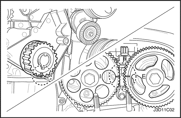
- Using crankshaft gear bolt, rotate the crankshaft clockwise until the timing mark on the crankshaft gear is aligned with the notch at the bottom of the rear timing belt cover.
- Align the camshaft gears with the notch on the camshaft cover.
Important : Use the intake gear mark for the intake camshaft gear and the exhaust gear mark for the exhaust camshaft gear since both gears are interchangeable.

- Loosen the automatic tensioner bolt. Turn the hex-key tab to relieve belt tension.
- Remove the timing belt.
Installation Procedure
- Align the timing mark on the crankshaft gear with the notch on the bottom of the rear timing belt cover.
- Align the timing marks on the camshaft gears, using the intake gear mark for the intake gear and the exhaust mark for the exhaust gear.

- Install the timing belt.
- Turn the hex-key tab in a clockwise direction to tension the belt. Turn until the pointer aligns with the notch.
- Install the automatic tensioner bolt.
Tighten
Tighten the automatic tensioner bolts to 25 N•m (18 lb-ft).
- Rotate the crankshaft two full turns clockwise using the crankshaft pulley bolt.
- Recheck the automatic tensioner pointer.
- Install the front timing belt cover.
- Install the front timing belt cover bolts.
Tighten
Tighten the front timing belt upper/lower cover bolts to 6 N•m (53 lb-in).
- Install the right engine mount brackt. Refer to "Engine Mounts"
in this section.
- Install the crankshaft pulley.
- Install the crankshaft pulley bolt.
Tighten
Tighten the crankshaft pulley bolt to 95 N•m (70 lb-ft) and turn the bolt another 30 degrees and 15 degrees using the angular torque gauge.

Rear Timing Belt Cover
Removal Procedure
- Remove the timing belt. Refer to "Timing Belt"
in this section.
- Remove the right engine mount bracket bolts
- Remove the right engine mount bracket.
- Remove the camshaft gears. Refer to "Camshaft Gears"
in this section.

- Remove the timing belt automatic tensioner bolt.
- Remove the timing belt automatic tensioner.
- Remove the timing belt idler pulleys.
- Remove the crankshaft gear.

- Remove the rear timing belt cover bolts.
- Remove the rear timing belt cover.
Installation Procedure
- Install the rear timing belt cover.
- Install the rear timing belt cover bolts.
Tighten
Tighten the rear timing belt cover bolts to 8 N•m (71 lb-in).
- Install the crankshaft gear.
- Install the timing belt idler pulleys.
Tighten
Tighten the timing belt idler pulleys bolts to 25 N•m (18 lb-ft).
- Install the right engine mount bracket supporter.
Tighten
Tighten the engine mount bracket supporter to 55 N•m (41 lb-ft).
- Install the timing belt automatic tensioner.
- Install the timing belt automatic tensioner bolt.
Tighten
Tighten the timing belt automatic tensioner bolt to 25 N•m (18 lb-ft).
| © Copyright General Motors Chevrolet Europe. All rights reserved |


