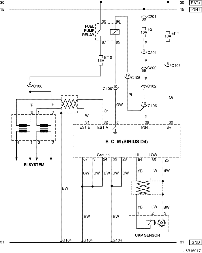
4. ECM (ENGINE CONTROL MODULE) : SIRIUS D4
1) BATTERY POWER SUPPLY, GROUND, EI SYSTEM & CKP SENSOR CIRCUIT
a. CONNECTOR INFORMATION
CONNECTOR NO
(PIN NO, COLOR) |
CONNECTING WIRING HARNESS |
CONNECTOR POSITION |
| C102 (11 Pin, White) |
Body – Engine Fuse Block |
Engine Fuse Block |
| C106 (20 Pin, White) |
Engine – Engine Fuse Block |
Engine Fuse Block |
| C201 (76 Pin, Black) |
I.P – I.P Fuse Block |
I.P Fuse Block |
| C202 (89 Pin, White) |
I.P – Body |
Left Driver Leg Room |
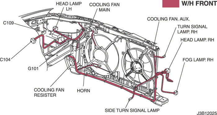
| G104 |
Engine |
Under Start Motor |
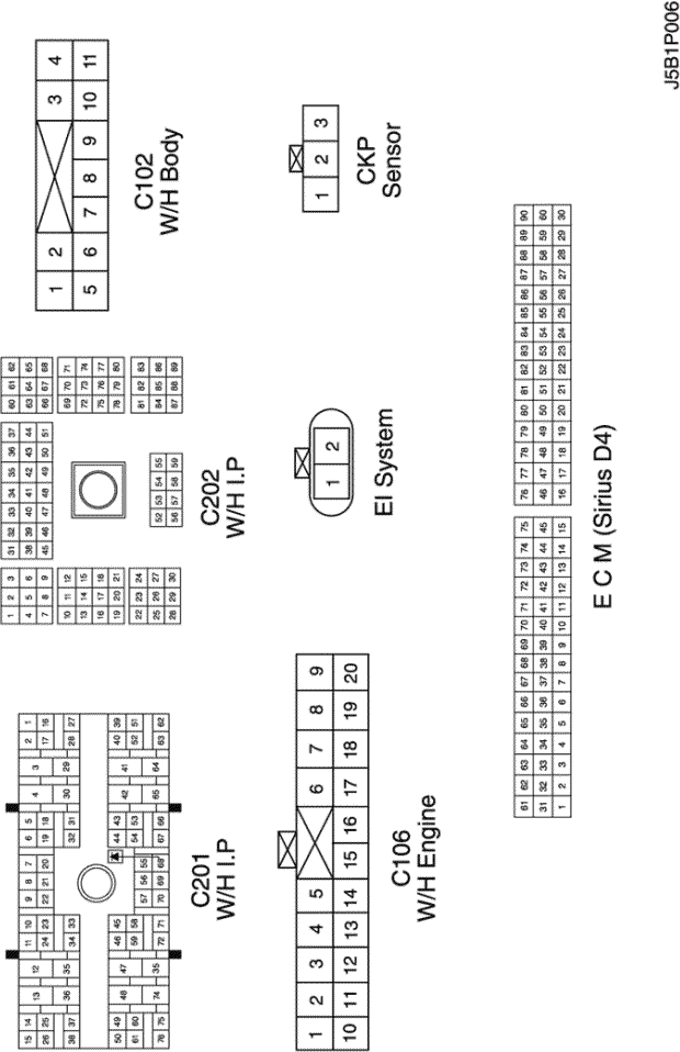
b. CONNECTOR IDENTIFICATION SYMBOL & PIN NUMBER POSITION
c. POSITION OF CONNECTORS AND GROUNDS
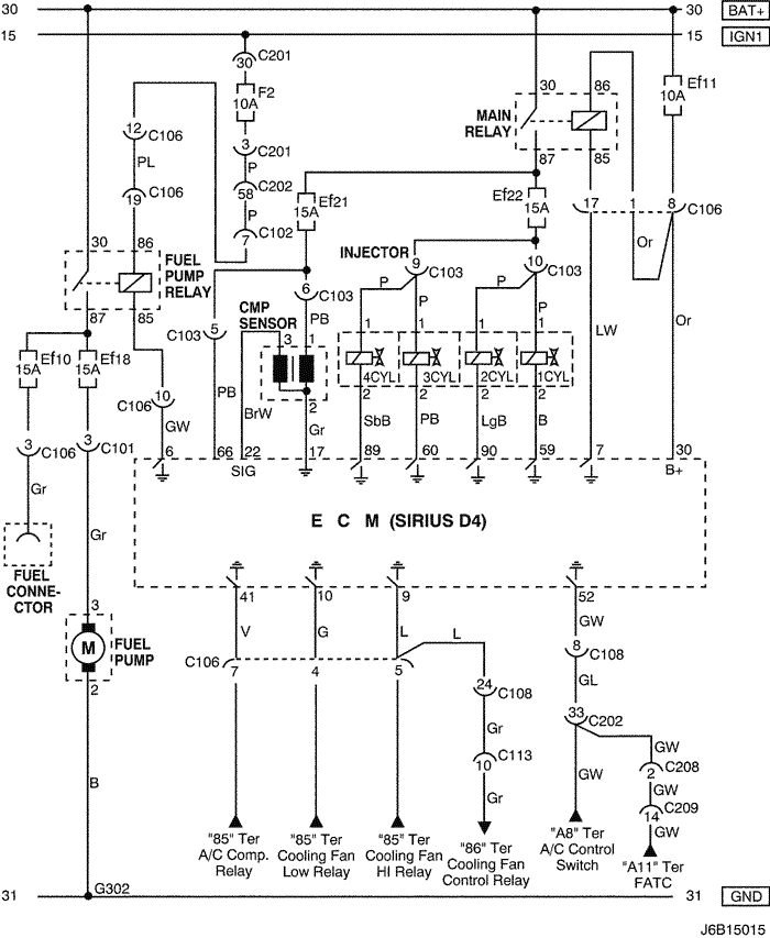
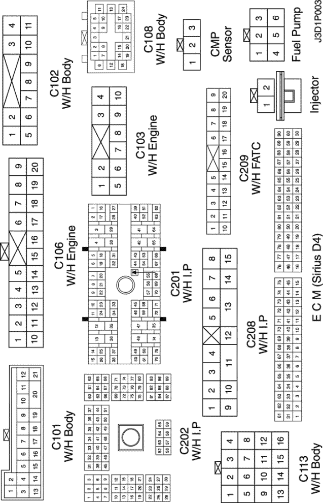
2) FUEL PUMP, INJECTOR, FUEL CONNECTOR & CMP SENSOR CIRCUIT
a. CONNECTOR INFORMATION
CONNECTOR NO
(PIN NO, COLOR) |
CONNECTING WIRING HARNESS |
CONNECTOR POSITION |
| C101 (21 Pin, White) |
Body – Engine Fuse Block |
Engine Fuse Block |
| C102 (11 Pin, White) |
Body – Engine Fuse Block |
Engine Fuse Block |
| C103 (10 Pin, White) |
Engine – Engine Fuse Block |
Engine Fuse Block |
| C106 (20 Pin, White) |
Engine – Engine Fuse Block |
Engine Fuse Block |
| C108 (24 Pin, Black) |
Body – Engine |
Left Engine Fuse Block |
| C113 (16 Pin, Black) |
Body – Front |
Behind ECM Bracket |
| C201 (76 Pin, Black) |
I.P – I.P Fuse Block |
I.P Fuse Block |
| C202 (89 Pin, White) |
I.P – Body |
Left Driver Leg Room |
| C208 (15 Pin, White) |
I.P – FATC |
Behind Glove Box |
| C209 (20 Pin, Black) |
FATC – FATC.Aux |
Between Heater Core and Evaporator Core |
| G302 |
Body |
Below Left C Pillar |
b. CONNECTOR IDENTIFICATION SYMBOL & PIN NUMBER POSITION
c. POSITION OF CONNECTORS AND GROUNDS
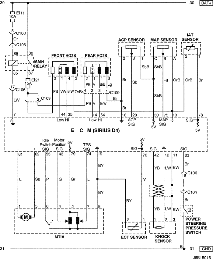
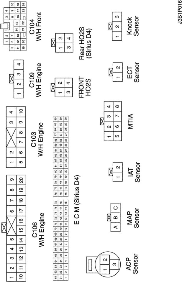
3) MTIA, SENSOR (ECT, KNOCK, IAT, MAP, ACP & HO2S) & POWER STEERING PRESSURE SWITCH CIRCUIT : EOBD
a. CONNECTOR INFORMATION
CONNECTOR NO
(PIN NO, COLOR) |
CONNECTING WIRING HARNESS |
CONNECTOR POSITION |
| C103 (10 Pin, White) |
Engine – Engine Fuse Block |
Engine Fuse Block |
| C104 (24 Pin, White) |
Front – Engine Fuse Block |
Engine Fuse Block |
| C106 (20 Pin, White) |
Engine – Engine Fuse Block |
Engine Fuse Block |
| C109 (4 Pin, White) |
Engine – Front |
Under Engine Fuse Block |
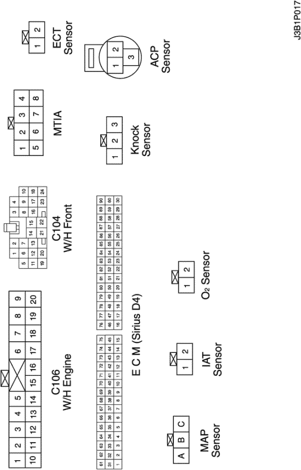
b. CONNECTOR IDENTIFICATION SYMBOL & PIN NUMBER POSITION
c. POSITION OF CONNECTORS AND GROUNDS
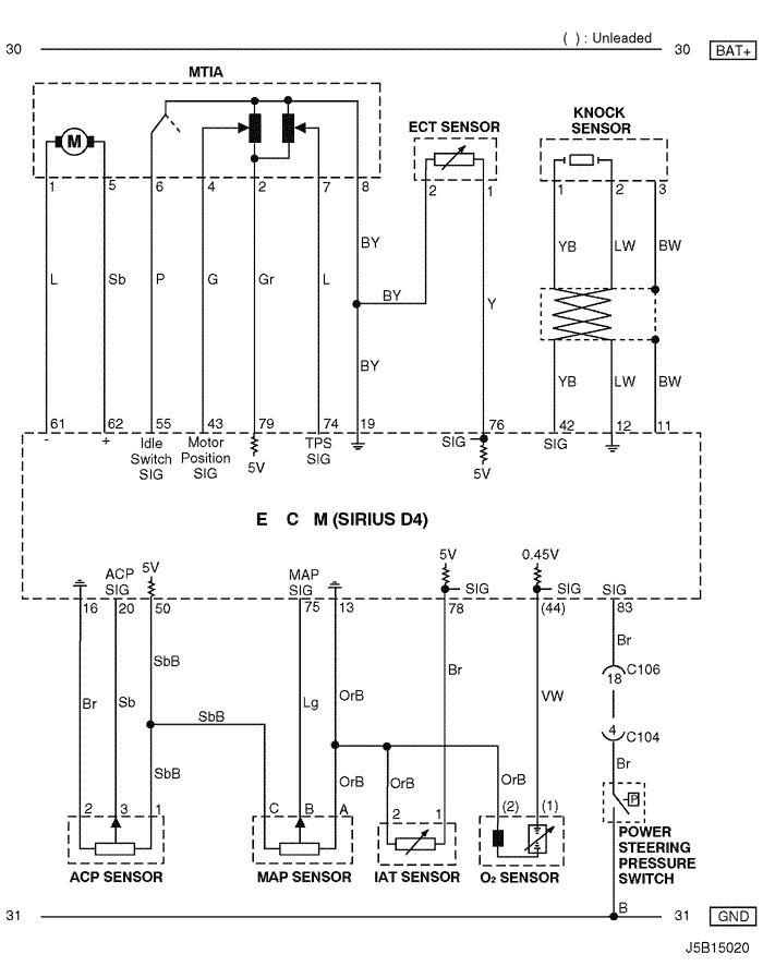
4) MTIA, SENSOR (ECT, KNOCK, IAT, MAP, ACP & O2) & POWER STEERING PRESSURE SWITCH CIRCUIT : NON EOBD
a. CONNECTOR INFORMATION
CONNECTOR NO
(PIN NO, COLOR) |
CONNECTING WIRING HARNESS |
CONNECTOR POSITION |
| C104 (24 Pin, White) |
Front – Engine Fuse Block |
Engine Fuse Block |
| C106 (20 Pin, White) |
Engine – Engine Fuse Block |
Engine Fuse Block |
b. CONNECTOR IDENTIFICATION SYMBOL & PIN NUMBER POSITION
c. POSITION OF CONNECTORS AND GROUNDS
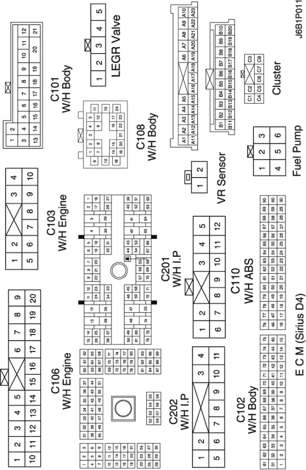
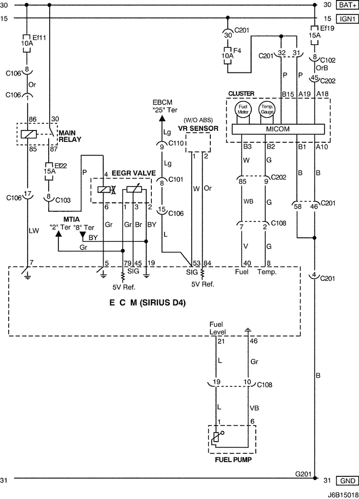
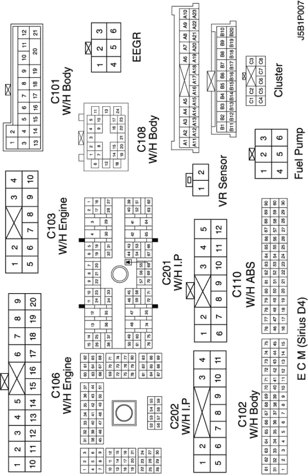
5) LEGR VALVE, VR SENSOR, CLUSTER & FUEL PUMP CIRCUIT : EOBD IV
a. CONNECTOR INFORMATION
CONNECTOR NO
(PIN NO, COLOR) |
CONNECTING WIRING HARNESS |
CONNECTOR POSITION |
| C101 (21 Pin, White) |
Body – Engine Fuse Block |
Engine Fuse Block |
| C102 (11 Pin, White) |
Body – Engine Fuse Block |
Engine Fuse Block |
| C103 (10 Pin, White) |
Engine – Engine Fuse Block |
Engine Fuse Block |
| C106 (20 Pin, White) |
Engine – Engine Fuse Block |
Engine Fuse Block |
| C108 (24 Pin, Black) |
Body – Engine |
Left Engine Fuse Block |
| C110 (12 Pin, White) |
ABS – Body |
Below Engine Fuse Block |
| C201 (76 Pin, Black) |
I.P – I.P Fuse Block |
I.P Fuse Block |
| C202 (89 Pin, White) |
I.P – Body |
Left Driver Leg Room |
| G201 |
I.P |
Left I.P Fuse Block |
b. CONNECTOR IDENTIFICATION SYMBOL & PIN NUMBER POSITION
c. POSITION OF CONNECTORS AND GROUNDS
6) EEGR VALVE, VR SENSOR, CLUSTER & FUEL PUMP CIRCUIT : EURO III
a. CONNECTOR INFORMATION
CONNECTOR NO
(PIN NO, COLOR) |
CONNECTING WIRING HARNESS |
CONNECTOR POSITION |
| C101 (21 Pin, White) |
Body – Engine Fuse Block |
Engine Fuse Block |
| C102 (11 Pin, White) |
Body – Engine Fuse Block |
Engine Fuse Block |
| C103 (10 Pin, White) |
Engine – Engine Fuse Block |
Engine Fuse Block |
| C106 (20 Pin, White) |
Engine – Engine Fuse Block |
Engine Fuse Block |
| C108 (24 Pin, Black) |
Body – Engine |
Left Engine Fuse Block |
| C110 (12 Pin, White) |
ABS – Body |
Below Engine Fuse Block |
| C201 (76 Pin, Black) |
I.P – I.P Fuse Block |
I.P Fuse Block |
| C202 (89 Pin, White) |
I.P – Body |
Left Driver Leg Room |
| G201 |
I.P |
Left I.P Fuse Block |
b. CONNECTOR IDENTIFICATION SYMBOL & PIN NUMBER POSITION
c. POSITION OF CONNECTORS AND GROUNDS
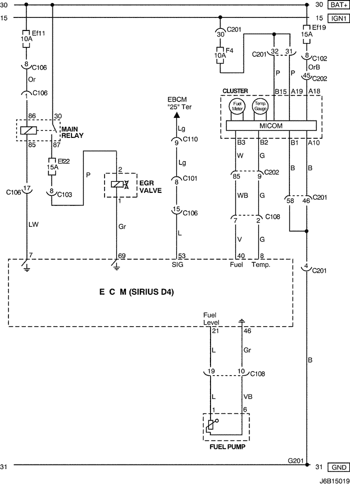
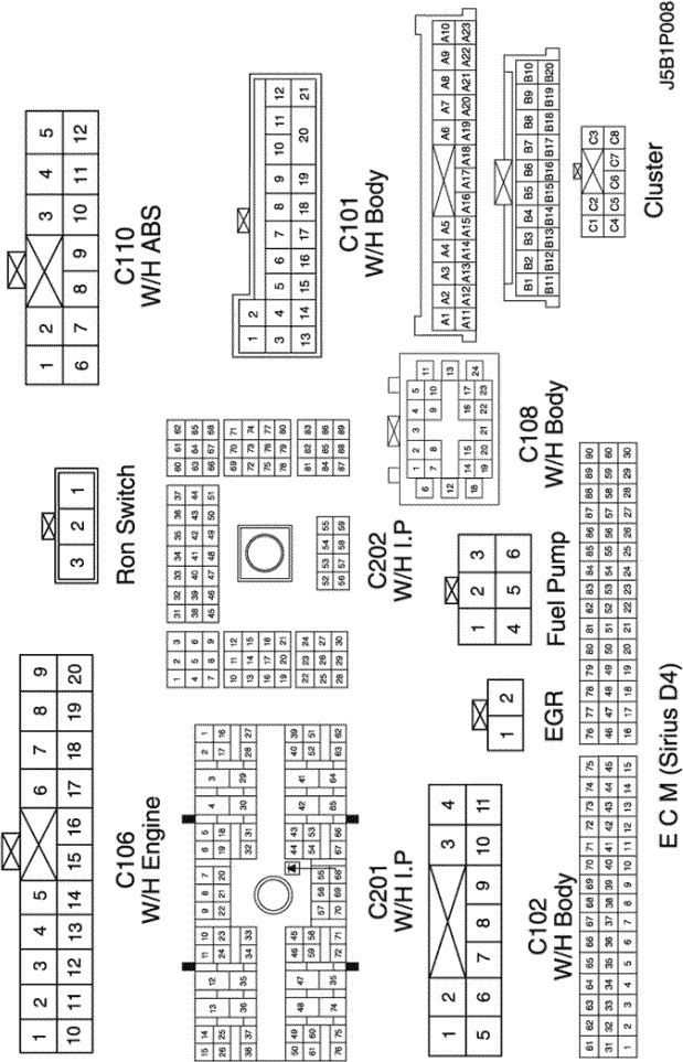
7) EGR VALVE, CLUSTER & FUEL PUMP CIRCUIT : NON EOBD
a. CONNECTOR INFORMATION
CONNECTOR NO
(PIN NO, COLOR) |
CONNECTING WIRING HARNESS |
CONNECTOR POSITION |
| C101 (21 Pin, White) |
Body – Engine Fuse Block |
Engine Fuse Block |
| C102 (11 Pin, White) |
Body – Engine Fuse Block |
Engine Fuse Block |
| C103 (10 Pin, White) |
Engine – Engine Fuse Block |
Engine Fuse Block |
| C106 (20 Pin, White) |
Engine – Engine Fuse Block |
Engine Fuse Block |
| C108 (24 Pin, Black) |
Body – Engine |
Left Engine Fuse Block |
| C110 (12 Pin, White) |
ABS – Body |
Below Engine Fuse Block |
| C201 (76 Pin, Black) |
I.P – I.P Fuse Block |
I.P Fuse Block |
| C202 (89 Pin, White) |
I.P – Body |
Left Driver Leg Room |
| G201 |
I.P |
Left I.P Fuse Block |
b. CONNECTOR IDENTIFICATION SYMBOL & PIN NUMBER POSITION
c. POSITION OF CONNECTORS AND GROUNDS
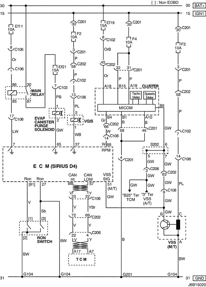
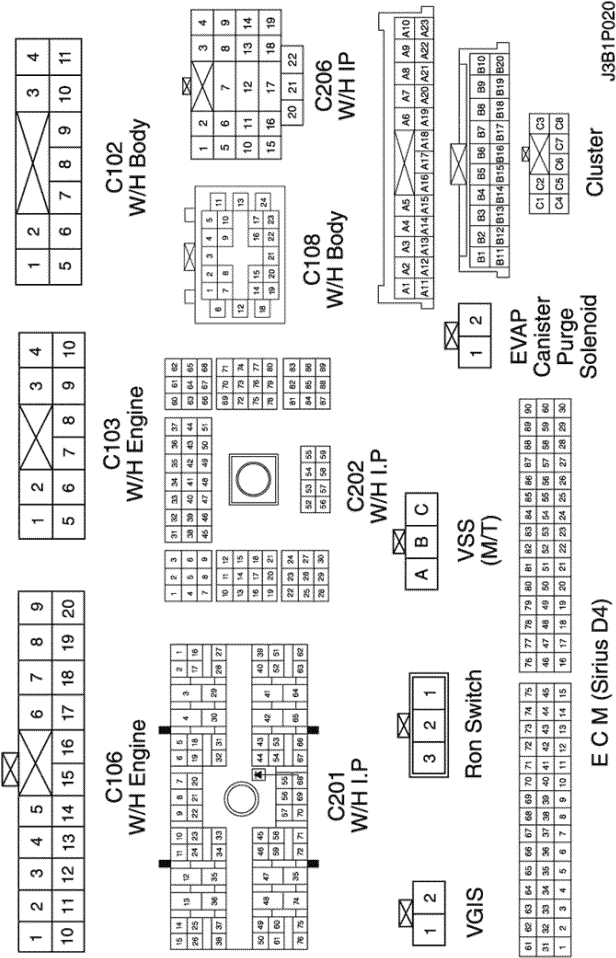
8) EVAP CANISTER PURGE SOLENOID, VGIS, CLUSTER, VSS, TCM & RON SWITCH CIRCUIT
a. CONNECTOR INFORMATION
CONNECTOR NO
(PIN NO, COLOR) |
CONNECTING WIRING HARNESS |
CONNECTOR POSITION |
| C102 (11 Pin, White) |
Body – Engine Fuse Block |
Engine Fuse Block |
| C103 (10 Pin, White) |
Engine – Engine Fuse Block |
Engine Fuse Block |
| C106 (20 Pin, White) |
Engine – Engine Fuse Block |
Engine Fuse Block |
| C108 (24 Pin, Black) |
Body – Engine |
Left Engine Fuse Block |
| C201 (76 Pin, Black) |
I.P – I.P Fuse Block |
I.P Fuse Block |
| C202 (89 Pin, White) |
I.P – Body |
Left Driver Leg Room |
| C206 (22 Pin, White) |
I.P – TCM |
Upper Driver Leg Room |
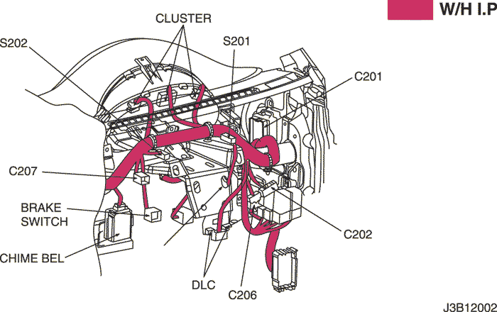
| S202 (Black) |
I.P |
Behind Cluster |
| G104 |
Engine |
Under Start Motor |
| G201 |
I.P |
Left I.P Fuse Block |
b. CONNECTOR IDENTIFICATION SYMBOL & PIN NUMBER POSITION
c. POSITION OF CONNECTORS AND GROUNDS
d. SPLICE PACK
S202
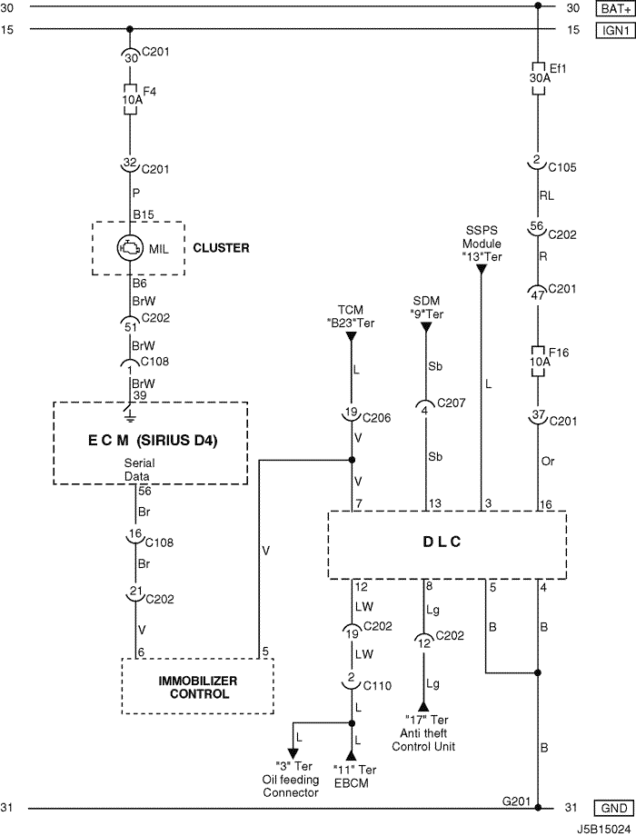
9) DLC MIL LAMP & IMMOBILIZER CONTROL CIRCUIT: W/ IMMOBILIZER
a. CONNECTOR INFORMATION
CONNECTOR NO
(PIN NO, COLOR) |
CONNECTING WIRING HARNESS |
CONNECTOR POSITION |
| C105 (4 Pin, White) |
Body – Engine Fuse Block |
Engine Fuse Block |
| C108 (24 Pin, Black) |
Body – Engine |
Left Engine Fuse Block |
| C110 (12 Pin, White) |
ABS – Body |
Below Engine Fuse Block |
| C201 (76 Pin, Black) |
I.P – I.P Fuse Block |
I.P Fuse Block |
| C202 (89 Pin, White) |
I.P – Body |
Left Driver Leg Room |
| C206 (22 Pin, White) |
I.P – TCM |
Upper Driver Leg Room |
| C207 (6 Pin, White) |
Air Bag – I.P |
Upper Right Driver Leg Room |
| G201 |
I.P |
Left I.P Fuse Block |
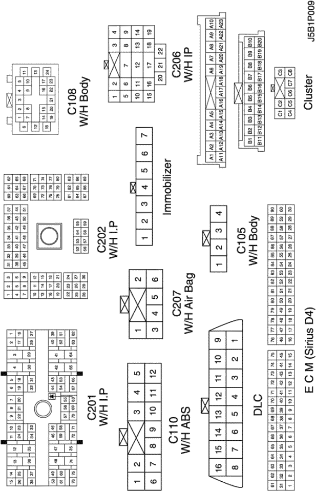
b. CONNECTOR IDENTIFICATION SYMBOL & PIN NUMBER POSITION
c. POSITION OF CONNECTORS AND GROUNDS
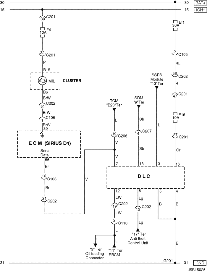
10) DLC & MIL LAMP CIRCUIT: W/O IMMOBILIZER
a. CONNECTOR INFORMATION
CONNECTOR NO
(PIN NO, COLOR) |
CONNECTING WIRING HARNESS |
CONNECTOR POSITION |
| C105 (4 Pin, White) |
Body – Engine Fuse Block |
Engine Fuse Block |
| C108 (24 Pin, Black) |
Body – Engine |
Left Engine Fuse Block |
| C110 (12 Pin, White) |
ABS – Body |
Below Engine Fuse Block |
| C201 (76 Pin, Black) |
I.P – I.P Fuse Block |
I.P Fuse Block |
| C202 (89 Pin, White) |
I.P – Body |
Left Driver Leg Room |
| C206 (22 Pin, White) |
I.P – TCM |
Upper Driver Leg Room |
| C207 (6 Pin, White) |
Air Bag – I.P |
Upper Right Driver Leg Room |
| G201 |
I.P |
Left I.P Fuse Block |
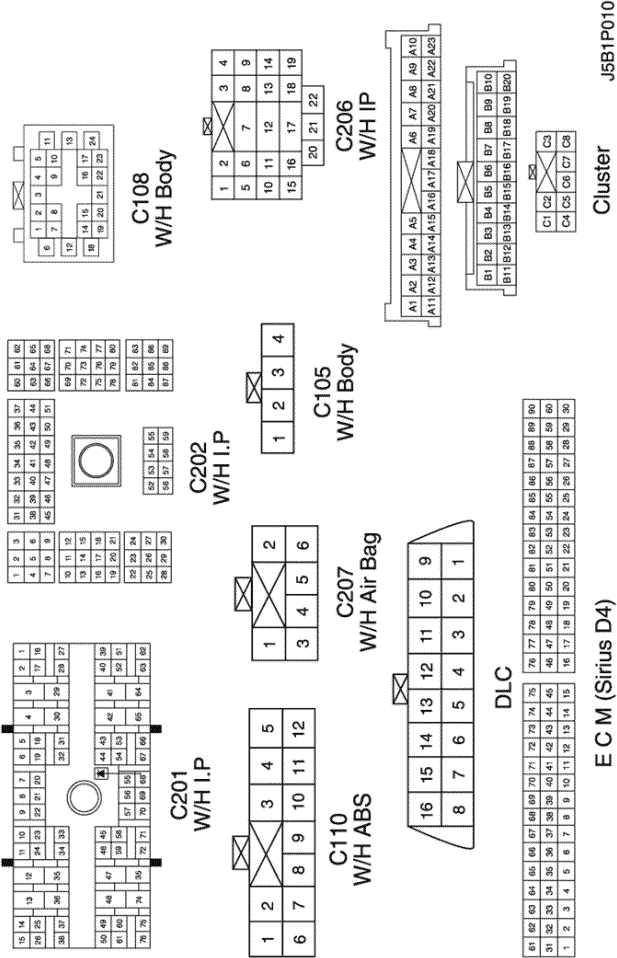
b. CONNECTOR IDENTIFICATION SYMBOL & PIN NUMBER POSITION
c. POSITION OF CONNECTORS AND GROUNDS
| © Copyright General Motors Chevrolet Europe. All rights reserved |