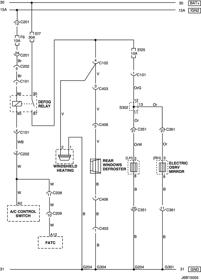
21. FRONT/REAR WINDOW DEFROSTER & OSRV MIRROR HEATING SYSTEM CIRCUIT
1) NOTCH BACK, HATCH BACK
a. CONNECTOR INFORMATION
CONNECTOR NO
(PIN NO, COLOR) |
CONNECTING WIRING HARNESS |
CONNECTOR POSITION |
| C101 (21 Pin, White) |
Body – Engine Fuse Block |
Engine Fuse Block |
| C102 (11 Pin, White) |
Body – Engine Fuse Block |
Engine Fuse Block |
| C201 (76 Pin, Black) |
I.P – I.P Fuse Block |
I.P Fuse Block |
| C202 (89 Pin, White) |
I.P – Body |
Left Driver Leg Room |
| C208 (15 Pin, White) |
I.P – FATC |
Behind Glove Box |
| C209 (20 Pin, Black) |
FATC – FATC.Aux |
Between Heater Core and Evaporator Core |
| C404 (8 Pin, White) |
T/Gate. EXT. – Body |
Inside Left C Pillar |
| C405 (8(10) Pin, White) |
T/Gate. EXT. – T/Gate |
Beside Left Rear Wiper Motor |
| C406 (6 Pin, White) |
T/Gate. EXT. – T/Gate |
Beside Left Rear Wiper Motor |
| C351 (33 Pin, Gray) |
Body – Front Light Door |
Under Driver A Pillar |
| C361 (33 Pin, Gray) |
Body – Front Right Door |
Under Co-Driver A Pillar |
| S302 (Brown) |
Body |
Left Driver Leg Room |
| G204 |
Body |
Below Left Driver Leg Room |
| G301 |
Body |
Below Co-Driver Cross Member Floor Panel |
| G402 |
T/Gate. EXT |
Inside Driver C Pillar |
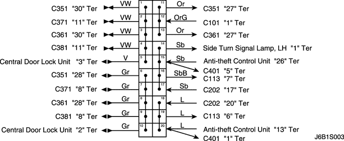
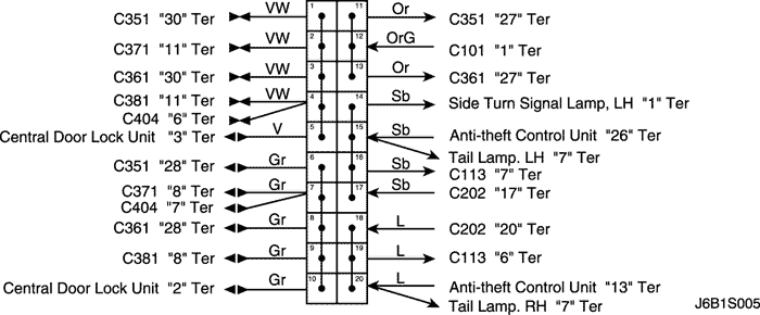
b. CONNECTOR IDENTIFICATION SYMBOL & PIN NUMBER POSITION
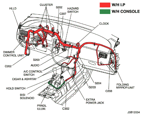
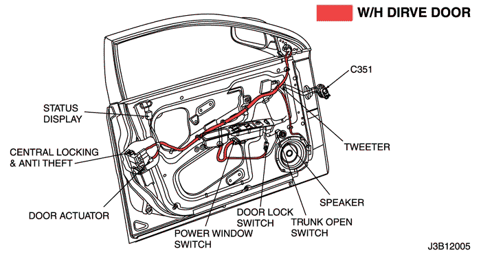
c. POSITION OF CONNECTORS AND GROUNDS
d. SPLICE PACK
S302 (NOTCH BACK)
S302 (HATCH BACK)
2) STATION WAGON
a. CONNECTOR INFORMATION
CONNECTOR NO
(PIN NO, COLOR) |
CONNECTING WIRING HARNESS |
CONNECTOR POSITION |
| C101 (21 Pin, White) |
Body – Engine Fuse Block |
Engine Fuse Block |
| C102 (11 Pin, White) |
Body – Engine Fuse Block |
Engine Fuse Block |
| C201 (76 Pin, Black) |
I.P – I.P Fuse Block |
I.P Fuse Block |
| C202 (89 Pin, White) |
I.P – Body |
Left Driver Leg Room |
| C208 (15 Pin, White) |
I.P – FATC |
Behind Glove Box |
| C209 (20 Pin, Black) |
FATC – FATC.Aux |
Between Heater Core and Evaporator Core |
| C351 (33 Pin, Gray) |
Body – Front Light Door |
Under Driver A Pillar |
| C361 (33 Pin, Gray) |
Body – Front Right Door |
Under Co-Driver A Pillar |
| C403 (4 Pin, White) |
T/Gate. EXT. – Body |
Inside Left C Pillar |
| C406 (4 Pin, White) |
T/Gate. EXT. – T/Gate |
Beside Left Rear Wiper Motor |
| S302 (Brown) |
Body |
Left Driver Leg Room |
| G204 |
Body |
Below Left Driver Leg Room |
| G301 |
Body |
Below Co-Driver Cross Member Floor Panel |
| G304 |
Body |
Below Left Rear Combination Lamp |
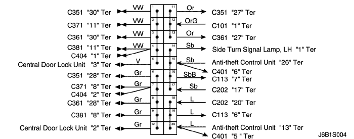
b. CONNECTOR IDENTIFICATION SYMBOL & PIN NUMBER POSITION
c. POSITION OF CONNECTORS AND GROUNDS
d. SPLICE PACK
S302 (STATION WAGON)
| © Copyright General Motors Chevrolet Europe. All rights reserved |