SECTION 5
ELECTRICAL WIRING DIAGRAMS
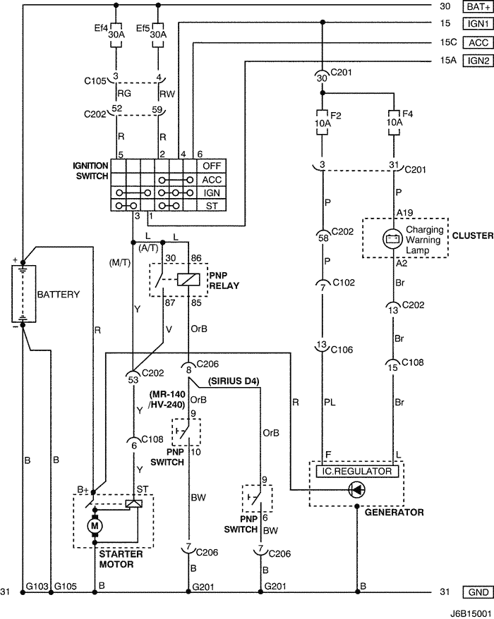
1. STARTING & CHARGING SYSTEM
1) BATTERY, IGNITION SWITCH, STARTER MOTOR, GENERATOR & PNP SWITCH CIRCUIT
a. CONNECTOR INFORMATION
CONNECTOR NO
(PIN NO, COLOR) |
CONNECTING WIRING HARNESS |
CONNECTOR POSITION |
| C102 (11 Pin, White) |
Body – Engine Fuse Block |
Engine Fuse Block |
| C105 (4 Pin, White) |
Body – Engine Fuse Block |
Engine Fuse Block |
| C106 (20 Pin, White) |
Engine – Engine Fuse Block |
Engine Fuse Block |
| C108 (24 Pin, Black) |
Body – Engine |
Left Engine Fuse Block |
| C201 (76 Pin, Black) |
I.P – I.P Fuse Block |
I.P Fuse Block |
| C202 (89 Pin, White) |
I.P – Body |
Left Driver Leg Room |
| C206 (22 Pin, White) |
I.P – TCM |
Upper Driver Leg Room |
| G103 |
Battery |
Left Battery |
| G105 |
Battery |
Under Start Motor |
| G201 |
I.P |
Left I.P Fuse Block |
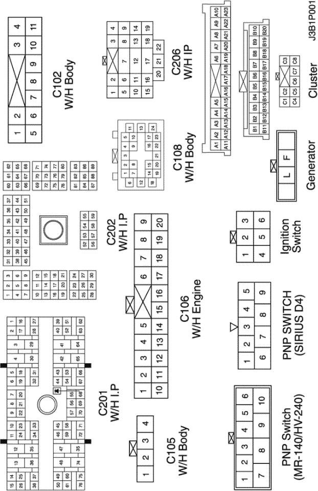
b. CONNECTOR IDENTIFICATION SYMBOL & PIN NUMBER POSITION
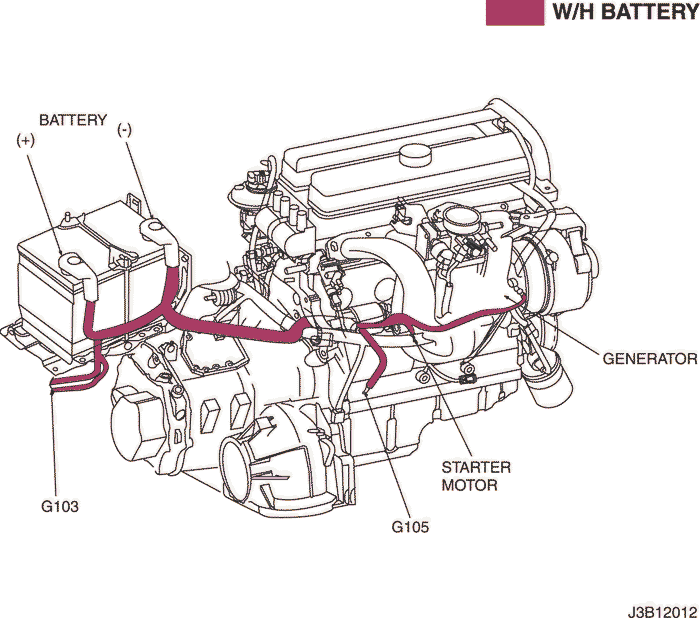
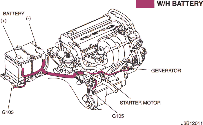
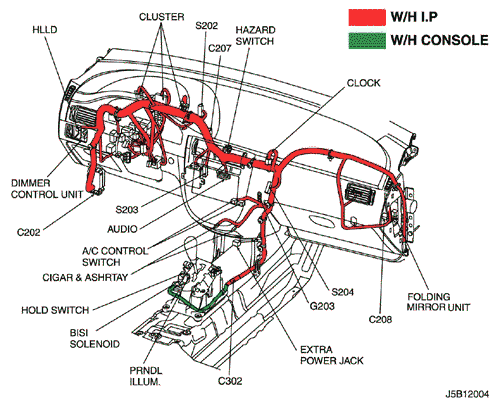
c. POSITION OF CONNECTORS AND GROUNDS
MR-140/HV-240
Sirius D4
| © Copyright General Motors Chevrolet Europe. All rights reserved |